Showing posts with label arduino. Show all posts

Saturday, October 1, 2011

XBee/Google Talk Garage Door

I had been thinking about doing a garage door controller project for years, but never found the time to work on it.  On occasion I had forgotten to close my garage door at night, and it wasn't until after hearing about a theft from a neighbor's garage that I decided to get started. Initially I just wanted a system to send notifications to my phone if the door was left open, but I decided door control would also be useful.

Edit: this project has since been updated to use my Arduino remote firmware solution. I no longer use Google Talk and instead use a simple REST API with embedded Jetty on a Raspberry Pi to send XBee messages to the Arduino. I use Cloud Messaging to send door events to my Android phone.


I did some research and found several garage door projects, using a variety of technologies: WiFi, Arduino, XBee and providing varying capabilities: monitor only, control only and both.  I wanted to be able to control and monitor the door from my Android phone.  I considered using WiFi.  This would have involved a web server on the Arduino, but Arduino cannot support https (TLS) due to memory/processing limitations, so that rules out essentially all APIs for sending notifications back to a mobile phone.  Another problem is accessing the web server from the internet would require configuring port forwarding from my router to the Arduino (not SSL), so bad idea.  Additionally, the Arduino Wifi hardware is quite expensive at this time.  I settled on XBee and Google Talk.  Of course Google Talk is supported on both Android and IPhone, so both me and my wife (IPhone) could control and monitor the door.  The downside to this solution is it does require running a server to bridge communication with both Google Talk and the Arduino.  For this I'm using my Sheevaplug (plug computer), since it's very low power (~3W). Edit: I swapped this with a Raspberry Pi a few years later.

Controlling a garage door requires a relay. Fortunately there's a good reference circuit for relays on the Arduino site.  I wired the relay to the Arduino and uploaded a simple script to verify I could make it open and close it. At first I wasted a lot of time troubleshooting what I thought was a circuit issue but turned out to be a bad breadboard. Note: the relay has a NO (normally open) and NC (normally closed). The garage door should be wired to the NO pin.


Note: The circuit above needs a 1K resistor from the transistor base to ground or it will not function!


I'm using magnetic sensors (reed switch) to provide door position.  These are the same sensors used in security systems and are very reliable.  The door sensors of course can tell you if your door is open or closed and identify a door failure (e.g. door started closing but failed to fully close).

I had to attach a 1x1 post to the joist to position the sensor at the open door position. The sensors close at around 1/2", so I connected them at around 1/4", allowing for sufficient door clearance.


The close-door contact was easily mounted on the wall. I used twist connectors to connect the sensor wire to the extension wire.


The door contacts should be wired to ground and one of the Arduino digital inputs. I'm using Arduino's built in pull up resistors to drive the pin HIGH when the circuit is open. When the magnetic reed switch closes, the pin will go LOW since it it grounded.  The sketch expects the close door sensor to be wired to digital pin 8 and the open door sensor to digital 9.


XBee Configuration

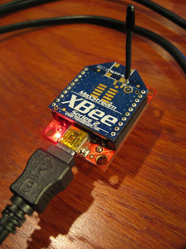
I used series 2 XBees in this solution, however series 1 would work just as well. The radios need to be configured with API firmware.  Refer to XBeeConfiguration. I recommend configuring your XBees to use encryption for security.


Software


You can download all the software for this project from my Google Code site


Arduino Sketch

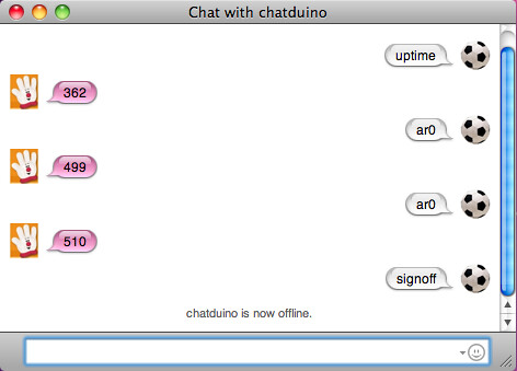
The loop function looks for incoming XBee requests (close door, open door, door status), and detects changes in the closed and open door magnetic contacts.  When the sketch receives an XBee packet (initiated by a Google Talk message), it performs the action (e.g. open door, close door, or status) and returns a acknowledgment packet.  Similarly, when it detects a change in the door sensors (e.g. door opening or closing), whether initiated from Google Talk or the garage door button, it sends the corresponding event to Google Talk.


The sketch requires only one change: update with the XBee address of the remote XBee.  Find COORD_MSB_ADDRESS and COORD_LSB_ADDRESS and replace with 64-bit address of the remote XBee (the one connected to the Java app).  The sketch assumes pins 8, 9, and 10 are used for the close-door sensor, open-door sensor and relay.  Adjust if necessary.

The sketch requires the xbee-arduino library to communicate with the XBee radio.  The library must be installed in your Arduino's "libraries" folder.  The project page includes installation instructions and information on getting started. 


#define STATUS_RESPONSE_TIMEOUT 500
#define DEBUG 0

uint8_t openContact;
uint8_t closeContact;

// state variables
bool doorFailure = false;
bool closing;
bool opening;
bool relayActivated;

// last time a contact fired
long lastDoorActionTime;
// last time the relay was activated
long lastRelayActionTime;

const uint8_t closePin = 8;
const uint8_t openPin = 9;
const uint8_t relayPin = 10;

// TX Commands
const uint8_t DOOR_OPEN = 4;
const uint8_t DOOR_CLOSED = 5;
const uint8_t DOOR_OPENING = 6;
const uint8_t DOOR_CLOSING = 7;
const uint8_t DOOR_FAILURE = 8;
const uint8_t DOOR_ALREADY_OPEN = 9;
const uint8_t DOOR_ALREADY_CLOSED = 10;
const uint8_t CMD_ACK = 11;
const uint8_t STARTUP = 12;

// RX Commands
const uint8_t DOOR_STATE_REQUEST = 1;
const uint8_t OPEN_DOOR_REQUEST = 2;
const uint8_t CLOSE_DOOR_REQUEST = 3;
// TODO 
const uint8_t GET_DOOR_STATS = 4;

const int MAX_DOOR_OPENCLOSE_TIME = 20000;
const uint8_t debounceDelay = 50;

uint16_t sendErrors = 0;

// Define NewSoftSerial TX/RX pins
// Connect TX of usb-serial device to NSS RX
uint8_t ssRX = 6;
// Connect RX of usb-serial device to NSS TX
uint8_t ssTX = 7;
// Remember to connect all devices to a common Ground: XBee, Arduino and USB-Serial device
NewSoftSerial nss(ssRX, ssTX);

XBee xbee = XBee();
XBeeResponse response = XBeeResponse();

// one byte payload
uint8_t payload[] = { 0 };

// TODO replace with address of your coordinator (Connected to the Java app)
uint32_t COORD_MSB_ADDRESS = 0x0013a41c;
uint32_t COORD_LSB_ADDRESS = 0x403ef3b1;

// Coordinator/XMPP Gateway
XBeeAddress64 addr64 = XBeeAddress64(COORD_MSB_ADDRESS, COORD_LSB_ADDRESS);
ZBTxRequest tx = ZBTxRequest(addr64, payload, sizeof(payload));
ZBTxStatusResponse txStatus = ZBTxStatusResponse();
// create reusable response objects for responses we expect to handle 
ZBRxResponse rx = ZBRxResponse();

void setup() {  
  // start serial
  xbee.begin(9600);
  
  if (DEBUG) {
    // start soft serial
    nss.begin(9600);
    nss.println("Startup");
  }
  
  // turn on internal pull-ups for magnetic switches
  pinMode(openPin, INPUT);
  digitalWrite(openPin, HIGH);
  
  pinMode(closePin, INPUT);
  digitalWrite(closePin, HIGH);
  
  pinMode(relayPin, OUTPUT);
  digitalWrite(relayPin, LOW);
  
  openContact = digitalRead(openPin);
  closeContact = digitalRead(closePin);
  
  opening = false;
  closing = false;
  doorFailure = false;
  lastDoorActionTime = 0;
}

void activateDoor() {
  digitalWrite(relayPin, HIGH);
  delay(200);
  digitalWrite(relayPin, LOW);
  
  relayActivated = true;
}

bool isDoorOpen() {
  // door is open only if open contact is closed and closed contact is open
  // 0 == closed contact, 1 == open contact
  return (openContact == 0) && (closeContact == 1);
}

bool isDoorClosed() {
  return (openContact == 1) && (closeContact == 0);
}

void handleXBeeResponse() {

  if (xbee.getResponse().getApiId() == ZB_RX_RESPONSE) {
       
    // now fill our zb rx class
    xbee.getResponse().getZBRxResponse(rx);
            
    // Make sure this is coming from our XBee (note: this is weak security.. using XBee encryption is highly recommended) 
    if (!(rx.getRemoteAddress64().getMsb() == COORD_MSB_ADDRESS && rx.getRemoteAddress64().getLsb() == COORD_LSB_ADDRESS)) {
      if (DEBUG) nss.println("WARN: unknown source address");
      return;
    }
     
    if (rx.getData(0) == OPEN_DOOR_REQUEST) {
      // open door
      if (isDoorClosed()) {
        if (DEBUG) nss.println("Opening door");
        activateDoor();       
        // tell the sender the request was successful  
        sendDoorEvent(CMD_ACK);                
      } else {
        // closed contact = 1 (open)
        // tell sender door is already open
        if (DEBUG) nss.println("Door already open!");
        sendDoorEvent(DOOR_ALREADY_OPEN);        
      }
    } else if (rx.getData(0) == CLOSE_DOOR_REQUEST) {
      // close door
      if (isDoorOpen()) {
        if (DEBUG) nss.println("Closing door");
        activateDoor();
        // tell the sender the request was successful
        sendDoorEvent(CMD_ACK);
      } else {
        if (DEBUG) nss.println("Door already closed!");
        // tell sender the door is already closed
        sendDoorEvent(DOOR_ALREADY_CLOSED);
      }
    } else if (rx.getData(0) == DOOR_STATE_REQUEST) {      
      sendDoorEvent((openContact & 1) + ((closeContact << 1) & 2));
    } else {
      // unknown command // TODO log
      if (DEBUG) nss.print("Unknown RX:");
      if (DEBUG) nss.println(rx.getData(0));
    }
  } else {
    // unsupported api -- TODO handle
    if (DEBUG) nss.print("Unsupported RX packet:");
    if (DEBUG) nss.println(xbee.getResponse().getApiId(), HEX);
  }
}

void sendDoorEvent(uint8_t message) {
  payload[0] = message;
  
  switch (message) {
     case DOOR_OPEN:
     case DOOR_CLOSED:
      lastDoorActionTime = millis();
      break;
  }
  
  // TODO set frame id with millis & 256
  xbee.send(tx);
  
  // after sending a tx request, we expect a status response
  // wait up to half second for the status response
  if (xbee.readPacket(STATUS_RESPONSE_TIMEOUT)) {
    // got a response!

    // check if series 1 or series 2 tx status       
    if (xbee.getResponse().getApiId() == ZB_TX_STATUS_RESPONSE) {
      xbee.getResponse().getZBTxStatusResponse(txStatus);

      // get the delivery status, the fifth byte
      if (txStatus.isSuccess()) {
        // good
      } else {
        if (DEBUG) nss.print("sendDoorEvent no ACK:");  
        // TODO resend with same frame id
        sendErrors++;
      }
    }      
  } else if (xbee.getResponse().isError()) {
    if (DEBUG) nss.print("sendDoor TX error:");  
    if (DEBUG) nss.println(xbee.getResponse().getErrorCode());
  } else {
    if (DEBUG) nss.print("sendDoor TX timeout");  
    // local XBee did not provide a timely TX Status Response -- should not happen if radio is configured and wired correctly
    // did you switch the TX/RX jumpers back to XBee?
    // is your baud rate correct?
    // in API mode?
  } 
}

// detect pin state change with debounce
bool pinChange(int pin, int current) {
  if (digitalRead(pin) != current) {
    
    // debounce
    delay(debounceDelay);
    
    // if state still the same, send event
    if (digitalRead(pin) != current) {
      return true;
    } else {
      // ignore spurious event
      // TODO log
      return false;
    }
  }
  
  return false;
}


void loop() {    
  // reads a packet from Serial, if data is available; otherwise continues on
  xbee.readPacket();
  
  if (xbee.getResponse().isAvailable()) {
    // got something
    handleXBeeResponse();
  } else if (xbee.getResponse().isError()) {
    if (DEBUG) nss.print("RX packet loop() error:");
    if (DEBUG) nss.println(xbee.getResponse().getErrorCode(), DEC);
  }

  // detect if open-door contact just tripped
  if (pinChange(openPin, openContact)) {
    // open-door contact tripped -- toggle it
    openContact = !openContact;

    // Remember that then the circuit is closed when the contacts meet, which makes the wire go to 0V (logical false).  An open contact is 5V (logical true)
    if (openContact) {
      // Open contact is now OPEN -- door is closing
      if (DEBUG) nss.println("Door closing");
      closing = true;
      lastDoorActionTime = millis();
      sendDoorEvent(DOOR_CLOSING);
    } else {
      // Open contact is now CLOSED -- door has completed opening
      if (DEBUG) nss.println("Door finished opening");
      opening = false;
      doorFailure = false;
      lastDoorActionTime = 0;
      sendDoorEvent(DOOR_OPEN);      
    }  
  }

  // detect if closed-door contact just tripped
  if (pinChange(closePin, closeContact)) {
      // closed-door contact tripped -- toggle it
      closeContact = !closeContact;  
      
      if (closeContact) {
        // Close contact is now OPEN -- door is opening
        if (DEBUG) nss.println("Door opening");
 // door opening
 opening = true;
 lastDoorActionTime = millis();
        sendDoorEvent(DOOR_OPENING);
      } else {
        // Close contact is now CLOSED -- door has finished closing
        if (DEBUG) nss.println("Door finished closing");
 closing = false;
 doorFailure = false;
 lastDoorActionTime = 0;
 sendDoorEvent(DOOR_CLOSED);
      }
  }
  
  if ((opening || closing) && (millis() - lastDoorActionTime) > MAX_DOOR_OPENCLOSE_TIME) {
     // Problem: door started opening or closing but did not complete with the expected time
     doorFailure = false;
     if (DEBUG) nss.println("Door failure");
     sendDoorEvent(DOOR_FAILURE);
     opening = false;
     closing = false;
  }
}


The Java Part

Unless you have multiple Google accounts, you'll need to create a Google account for the garage door (e.g. mygaragedoor@gmail.com). If you reuse an existing account, remember that anyone that is in your roster list (friends), will be able to control your door, unless your remove them. For this reason it's better to create a separate account.

There are a few changes that need to be made in the Java app. Open GarageDoor.java (I recommend using an IDE such as Eclipse or Netbeans) and make the following changes. Find garageDoorAddress and replace with the 64-bit address of the garage door XBee. Find xbee.open("yourcomport", 9600); and enter the com port of XBee connected to your computer (Coordinator).
In initGoogleTalk, add a roster friend for each Google account that should be allowed to control the Garage Door, for example:

xmppClient.addRosterFriend("yourpersonalgmailaccount@gmail.com");

The software will automatically subscribe to and accept messages from this Google account. Only Google accounts specified here will be able to control and receive messages from the garage door.

Find the following line:

xmppClient.connect(new GtalkConnector("mygaragedoor@gmail.com", "password"), new MessageListener() {

and replace with the email/password of the Google account that was created for the garage door.

Once all changes have been made, you can run the application from your IDE.  All required libraries are included in the software download, so your IDE should find them automatically.  If not, add all JAR file in the "lib" folder.


The Google Talk commands are simple for easy operation with a mobile phone.  The commands are o=Open Door, c=Close Door, and s=Door Status. If you send a command that is not understood, the menu is returned.  Disregard the x (Extended menu), which I never got around to implementing.


In addition to sending open/close door events via Google Talk, the Java application will send a reminder if the door is left open for 10 minutes.

Security

Google Talk authentication and communication occurs over TLS (transport layer security), so you can consider it to be quite secure, to the extent that you protect your credentials and choose a strong password. Additionally, only users that you specify can send messages to the garage door account, so you don't have to worry about a spammer playing with your door.  You could add additional security by requiring a pin number to be entered for each door control request.

The Arduino Sketch is configured to only accept XBee packets from your radio. It does this by checking the source address (64-bit serial high/low). This however is not good security as it could be defeated, but is somewhat safe in that Digi firmware will not let you spoof addresses. I strongly recommend using XBee's built-in support for encryption.

Case

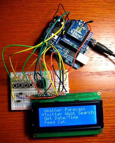
For the case I found a plastic pizza dough container from Whole Foods in my recycle bin. You can see I'm lazy by using a breadboard instead of assembling the components on protoboard. I recommend mounting the Arduino such that you can access the jumpers and USB cable for updating the sketch.

Parts

  • Omron G5SB Relay http://www.sparkfun.com/products/10509 This 5V relay is Arduino safe, in that the coil impedance is high enough that the Arduino can safely power it.
  • 2N2222A transistor http://search.digikey.com/scripts/DkSearch/dksus.dll?Detail&name=497-2598-ND Doesn't have to be this exact one
  • Couple 1K Resistors.  I'm guessing you have some of these
  • 1N4004 Diode http://search.digikey.com/scripts/DkSearch/dksus.dll?Detail&name=1N4004FSCT-ND Can also be found at Radio Shacks, in the US
  • 2 Magnetic door contacts. I got mine on ebay: http://cgi.ebay.com/5-Set-Door-Window-Contact-Magnetic-Reed-Switch-Alarm-/110716359054?pt=LH_DefaultDomain_0&hash=item19c735918e#ht_2557wt_1114 Keep in mind that if you order from China, be prepared to wait 3 weeks, unless of course you live in China.
  • Low voltage wire to connect Arduino circuit to the garage door unit and magnetic sensors. Measure first to get an idea of how much you need. I bought a 65' spool of 20 gauge at Home Depot which was more than enough
  • Wire connectors caps, similar to this http://www.homedepot.com/h_d1/N-5yc1v/R-100628936/h_d2/ProductDisplay?langId=-1&storeId=10051&catalogId=10053
  • Obviously you'll need two Series 2 XBees, one Arduino or clone (e.g. RBBB). A USB Explorer or equivalent for the PC side, and a XBee socket or XBee Shield to interface with the Arduino.
  • 9V Arduino power supply and possibly an extension cord.
  • Standoffs and zip ties to mount the Arduino in the enclosure.
  • Some screws and washers to mount the enclosure to wall

Saturday, November 21, 2009

Chatduino: An AIM Client for Arduino/Wiznet 5100

This is an AIM instant messenger client for Arduino/Wiznet 5100, which allows you to communicate with your Arduino project from anywhere on the internet, in near real-time. You can communicate with your project through any AIM client or even your cell phone by using text messaging with Mobile AIM, and since communication is channeled though the AIM server, both the Arduino+Wiznet and chat client can exist behind firewalls.


At first I looked into creating an Arduino library for XMPP/Jabber. This would allow you to connect to Google Talk/App Engine or any other XMPP service. The problem which this approach is most XMPP services require TLS for security, and TLS isn't going to happen on an ATmega328 (thinly veiled challenge going out to anyone who can prove otherwise). I looked at a few other chat services and finally settled on AOL instant messenger (AIM) because it's very popular and the protocol (TOC) is easy to implement on the Arduino. Although the protocol is proprietary, it is well understood and there are many open source libraries/apps available.

Hardware

Arduino + Wiznet W5100 Ethernet chip. This comes packaged together nicely with the Arduino Ethernet Shield. See below for parts.

Installation and Setup

If you don't already have an AIM account, go to http://www.aim.com/ and register for a free screen name.

Download Chatduino and open in Arduino

The official Arduino ethernet library does not support DHCP. Because of this we need to specify the IP address of the Wiznet. For example:
static byte ip[] = { 192, 168, 1, 99 };
Choose an IP address that is not in use and one that is not used by DHCP. I chose 192.168.1.99 since my router (Linksys) uses 192.168.1.100 and up for DHCP.

The Arduino ethernet library also does not support DNS, so we need to use the IP address of the AIM server. I have provided the two IP addresses for the TOC domain (toc.oscar.aol.com) at this time. Either should work but these could change over time. If you are having connection problems you may need to do a domain lookup on toc.oscar.aol.com to get the new IP addresses.
//static byte server[] = { 64, 12, 202, 14 };
static byte server[] = { 64, 12, 202, 7 };
The default port of the AIM server is 5190. If you are having connectivity issues, it's possible that your network is blocking this port. Try using port 80 instead.

Update: Some users have suggested an alternate Ethernet library that supports both DNS and DHCP. You might want to give this a try.

Scroll down toward the bottom of the sketch and specify your screen name and password:
char screenName[] = "yourscreenanme";
char pass[] = "yourpassword";
Specify the length of the message array. You will still be able to receive messages that are larger but of course only "msgLen" of the message will be stored in the array. Remember that the ATmega has limited memory (1K), so you don't want to make the arrays excessively large.
const uint16_t msgLen = 50;
Specify the length of the "from" screen name. This value should be at least (+1) larger than the largest screen name you expect.
const uint16_t fromLen = 18;
Now add your code inside the if (readMessage(from, fromLen, msg, msgLen) == 0) { block. This statement evaluates to true whenever a message is received.

The from string contains the screen name that sent the message and the msg string contains the message. For example:
if (strcmp(from, "myscreenname") == 0) {
// a message from "myscreenname"
if (strcmp(msg, "get temp") == 0) {
// return analog reading of temp sensor
itoa(analogRead(0), msg, 10);
sendMessage(from, msg);
}
else if (strcmp(msg, "turn on led") == 0) {
// turn on led
digitalWrite(ledPin, HIGH);
sendMessage(from, "ok");
}
}
Because of the bi-directional nature of chat, it's also possible to send messages based on external events. Here's an example:
//Place outside of readMessage block
if (digitalRead(motionPin) == HIGH) {
sendMessage("anyscreenname", "motion detected!");
}
Now you should be able to upload your Sketch and it should sign-on to AIM.

I have provided a few functions that you may find useful. The processPinRequest function provides I/O pin control. For example ar5 returns an analogRead of pin 5, and dw4=1 performs a digitalWrite(4, HIGH). Analog write (PWM) and digital read are also supported. It's recommend that you restrict write operations to verified screen names. To accomplish this, you can set authUser to a specific screen name that is allowed to manipulate the I/O pins. By default all users are allowed to perform pin readings. Refer to the function comments for more information.

It is highly recommended to sign-off from AIM before uploading a new sketch or powering off the unit, or AIM gets confused and may not allow reconnects for a period of time. You can sign-off by sending a "signoff" message. I've encountered a few instances where the Sketch failed to connect to AIM after it was previously connected and signed off. Hitting the reset button a few times seems to fix this issue (wait at least 15 seconds between resets).

The Sketch will automatically attempt to reconnect if disconnected from AIM. You can send the "reconnects" message to get the number of reconnects. I've been running the service for over a week with zero reconnects.

Serial debug can be turned on by setting #define CHATDUINO_DEBUG to 1 at the top of the sketch.

Note: I am using the Wiznet module (WIZ812MJ) directly, without a shield. This means I need to explicitly reset the device on startup. This is done by connecting the Wiznet reset pin to 9 (use a resistor, 1K or so), and setting #define WIZNET812MJ (top of sketch) to 1. The Arduino Ethernet Shield will reset automatically and does not require this step.

Parts

Seeedstudio currently has the best price on the Arduino Ethernet Shield ($29), although they are out of stock at the time of this writing. This is actually a clone but is functionally equivalent to the official shield.

NKC Electronics sells the official Arduino Ethernet Shield for $40 or you can get their version for $32 (requires assembly).

Whatever you choose, make sure you get a Wiznet based device and not Microchip's ENC28J60.

If you're looking for the most cost effective solution (less then the cost of the ethernet shield alone), and you don't mind wiring it together, I recommend an Arduino clone, such as Modern Device's RBBB (~$12) and the WIZNET812MJ (~$21). This setup requires a breadboard/protoboard, 3.3V power, some female/male jumpers, and a USB-serial device to program the RBBB.

Considerations

Currently the sketch only processes incoming messages. Other commands: CONFIG2, UPDATE_BUDDY2, PING etc. are ignored. In a future release I would like to support buddy list updates, which would allow you to receive notifications when your friends signon/signoff.
Other improvements may include using EEPROM to save memory and not blocking on readMessage if the receive buffer is empty. Of course at this time it's just a sketch but if people find it useful, I may release it as an Arduino library.

Friday, August 7, 2009

Droplet

Several months ago I released XBeeArduinoService. Since then I have been working on the next version. It's now available and has a new name: Droplet.

What's New
  • Menu/Navigation: The first version relied on a dedicated button for each service. This worked but doesn't scale well since you will quickly run out of buttons. Now it uses a menu to display the available services. Along with the menu are four buttons for navigation: Next, Previous, Select, and Escape.


  • Pagination: Previously, each message was limited to 80 characters, which of course is not much. Now messages that exceed 80 characters are formatted into multiple pages. A multi-page message is indicated by an arrow "⇾" character in the bottom right corner. When this character is present, selecting the Next button loads the next page.

  • Push Services: these are services that run in the background and send messages (or droplets) to the remote. I have written push services for Twitter, Gmail and Google Calendar. Note: these are different from pull services, which are user initiated and are listed on the menu.
  • History: You can now access previous messages that were sent to the LCD. This is helpful if you clicked the Next button too quickly, or you want to see any messages that were sent while you were away (e.g. missed tweets, calendar events). Selecting the Previous button while any message is displayed will load the previous message.
  • New Services: Twitter, Twitter Search, Google Calendar, IMAP "Push" Email (e.g Gmail) and Top News.
  • Light and Sound: A red LED flashes when a Push Service sends a message (tweets/calendar/email) and optionally a buzzer can sound. The Google Calendar service sounds the buzzer if "#buzzer#" appears in a Google Calendar event description. It effectively becomes a Google alarm clock when using the buzzer option with Google Calendar.
  • Multiple Remotes: This version includes better support for multiple remotes. You can use the XBee broadcast address (0x00000000ffff) to send messages to all remotes or target one or more specific remotes.
A Demo

Parts

For this version I added the following parts:
Circuit

In an attempt to not repeat myself, in this entry I'm only going to cover what's new, so you'll want to familiarize yourself with the previous version.

Now to wire up the new parts. Connect the buzzer to the Arduino Analog 0 and the negative terminal to GND. Yeah, that's right, Arduino lets you repurpose the Analog pins as Digital outputs. Analog 0-5 can accessed as Digital pins 14-19. Pretty neat, huh? Here's some more info.

Wire the LED to the Arduino Digital 5 pin and GND, placing your resistor in series.

Wire each push button to GND and the following Arduino Pin:

Next: Digital 2
Previous: Analog 1 (We are also repurposing this pin to be Digital, same as the buzzer pin)
Select: Digital 3
Escape: Digital 4

In case you're wondering whether it's safe or even a good practice to connect a button without a pull-up/down resistor, keep reading. In the previous version I was using a pull up resistor to drive the pin to a known state while the button was in its normally-open position. It turns out there's an easier way to do this by using the Arduino's internal pull up resistors. The pull-up resistors are enabled by setting the pin mode to INPUT, then turning them on with a digital write HIGH. In this configuration, the pin will read HIGH until the button is depressed, when it will read LOW, and we don't need to mess with any resistors! Thanks to todbot for this technique.

XBee Configuration

The XBee configuration is identical to the previous version.

Software

Download the project software from Google Code. This download includes everything you need to get it up and running except for Java (requires Java 5) and Eclipse. Eclipse is recommended but isn't required and if you are experienced with Java you can use your IDE of choice or run from the command-line. Being Java, this software will run on a variety of platforms (Windows, Mac, Linux etc.). The only limiting factor is the RXTX serial library and I've included binaries for Windows, Mac and Linux (Arduino uses RXTX also).

As before, you need to install two Arduino libraries. XBee-Arduino for XBee communication and LCD4x20 to display text on the LCD. Unzip the downloaded file and you will find these files in the "Arduino" folder of the project:

LCD4x20-781.zip
xbee-arduino-0.1.2.zip

Unzip each file and install in your ARDUINO_HOME/hardware/libraries folder
(where ARDUINO_HOME is the location of Arduino on your system. On my machine it's /Users/andrew/Documents/devsoft/arduino-0016/hardware/libraries)

After installation, you should have XBee and LCD4x20 folders under ARDUINO_HOME/hardware/libraries. Note: the LCD library was updated since the previous version, so if you have the previous version, delete the LCD4x20.o file, to force Arduino to recompile the library.

Now upload the Sketch to the Arduino. The sketch (DropletRemote.pde) is located in "Droplet/Arduino/DropletRemote". But before uploading we need to make one minor change. Find the following line:

XBeeAddress64 addr64 = XBeeAddress64(0x0013a200, 0x403e0f30);

and replace the 64-bit address with the (SH + SL) of your XBee coordinator. See the previous blog entry for info on how to get your SH + SL address. Remember to put the XBee Shield jumpers in the "USB" position to upload the Sketch and return the jumpers to the "XBee" position after a successful upload.

Now for the Service Gateway. As before, create an Eclipse project and point it to the Droplet folder. Refer to the previous version if necessary. There are just a few things to change in the Java file. Open DropletDemo.java in Eclipse. This file is located in "/src/com/rapplogic/droplet/impl/" In this file you'll need to specify the address of the remote XBee for the variable "remoteXBee". Also specify the COM port and baud rate of the XBee coordinator.

Since we are using Google and Twitter, you'll need to specify the login information to access your accounts if you want these services. Open google.credentials and specify your Google/Gmail username and password. Now open twitter.credentials and specify your Twitter username and password.

The demo starts up all available services, but possibly you are not interested in running them all. If this is the case, comment out the services you do not want with the Java comment syntax "//" at the beginning of the line. Note: the weather services requires a zip code, so if you are using these services search for "20175" and replace with your zip code. Save the file.

Ok now we're ready to run it. Power up the Arduino, connect the XBee coordinator to the computer and start the application by selecting "Run" from the "Run" menu. Choose one of the services on the LCD menu and click the Select button and you should see the resulting message on the LCD. Woohoo!

Creating Custom Services

The service API has changed significantly since the last version, making it easier to write your own Droplet services. First you need to decide whether you want to create a Pull Service or Push Service. A Pull Service is listed on the menu and is only activated by a button press on the remote. A Push Service runs in the Java application on a periodic basic and sends messages to the remote.

Pull Services

Adding a Pull Service requires an implementation of the PullService interface. This can be accomplished by creating a class that implements the interface, or for simple services, using an anonymous inner class, as in this example. The PullService interface requires that you implement the execute method:

public IContent execute(Integer serviceId, XBeeResponse response, ServiceContext serviceContext) throws Exception

This method provides the following arguments:
  • serviceId: this is the menu position of the service, starting at 0. If you have a single service that supports multiple menu items, you'll need to refer to this variable.
  • response: the XBeeResponse received from the Arduino. This is useful if you need to know the remote that sent the request or any of details of the transmission, such as RF strength.
  • serviceContext: this object exposes several methods of the Droplet API, the most important method for Pull Services being the format method. This method is acessed by serviceContext.getFormatter().format(String); it takes an arbitrary String, of any length, and formats it for display on a LCD. This method will handle pagination if the String doesn't fit on the LCD. This method also optimizes the String for display on the LCD, according to the PaginationRules class. (see Javadoc for details of all Droplet classes/interfaces).
Within this method you can do whatever you need (send an email, turn on your sprinklers etc.), but the service method must return in a timely manner, specifically 6 seconds, although this is configurable. This method returns an instance of IContent, which really a fancy container of the text to be displayed on the LCD. You can return null but the framework will still send a default message to the remote. Here's an example:
PullService time = new PullService() {
public IContent execute(Integer serviceId, XBeeResponse response, ServiceContext serviceContext) throws Exception {

return serviceContext.getFormatter().format("The current time is " + new Date() + ". You will see this response on your LCD after the service executes. You can even use linefeed characters \n to format the response");
}
};
The last activity is to register your service with the Droplet framework. The first argument of the register method is the position of the item in the menu. The position starts at 0, so the second item in the menu is 1.
droplet.registerPullService(1, time);
Now you will need to add your new service as the second menu item in the Arduino Sketch. After the Sketch has been uploaded you should be able to select the second menu item on the remote and it will activate your service. Note: if you change the number of items in the menu, make sure to update the menuSize variable to the new number.

Push Services

There are three types of Push Services: Realtime, Delayed and Runnable. A Realtime service returns a message to be delivered immediately to the remote. A Delayed service returns a message to be delivered to the remote at some point in the future. And finally, a Runnable service occupies a dedicated thread and runs all the time. The Realtime and Delayed services are further divided into two subtypes: Recurring and OneTime, where Recurring services are invoked periodically, and OneTime services are invoked only once.

To create a Realtime service, you will need to extend the RealTimeAlertPushService and implement either the RecurringService or OneTimeService interface. To simplify things, there is a SimpleRealtimeRecurringPushService class that extends RealTimeAlertPushService and implements RecurringService, along with some default values.

Unlike Pull Services, Push Services need to know the 64-bit address of the remote XBee that should receive the message. Optionally you could specify a broadcast address to send to all remotes. Here's an example of a Push Service that sends a wake up alert every weekday at 6 AM. The service returns an instance of the Alert class. An Alert contains properties for determining whether or not the LED should flash or the buzzer should sound. While Pull Services always return a message to the LCD for display, Push Services may return null, in which case nothing is sent.
XBeeAddress64 remoteXBee = new XBeeAddress64(0x00,0x13,0xa2,0x00,0x40,0x0a,0x3e,0x02);

SimpleRealtimeRecurringPushService wakeUp = new SimpleRealtimeRecurringPushService(remoteXBee) {

@Override
public Alert execute(ServiceContext serviceContext) throws Exception {
Calendar cal = Calendar.getInstance();

int dayOfWeek = cal.get(Calendar.DAY_OF_WEEK);

if (dayOfWeek == Calendar.SATURDAY || dayOfWeek == Calendar.SUNDAY) {
// it's the weekend. you can sleep in
return null;
}

int minute = cal.get(Calendar.MINUTE);
int hour = cal.get(Calendar.HOUR_OF_DAY);

if (hour == 6 && minute == 0) {
// wake up!
Alert alert = new Alert();
alert.setContent(serviceContext.getFormatter().format("It's Wake Up Time !!!!!!"));
alert.setRemoteXBeeAddress(this.getRemoteXBeeAddress());
// flash the LED
alert.setFlashLed(true);
// sound the alarm!
alert.setSoundAlarm(true);

return alert;
}

// not time yet
return null;
}
};

// run once a minute (delay is in milliseconds, so multiple by 1000)
wakeUp.setDelay(60000);
wakeUp.setName("WakeUp");

// register the service with the framework
droplet.registerPushService(wakeUp);
For more examples, look in the com.rapplogic.droplet.impl.services.* packages for the source code to all services.

What's Next?
  • Plug Computer. I recently received a SheevaPlug. SheevaPlug is a low power ARM computer, about the size of a wall adapter, that runs Linux. My goal is to run the Droplet Java application on the SheevaPlug.
  • Extra Pins. After everything is wired-up, we still have 6 Arduino pins left: 4 Analog or Digital (Analog 2-5, Digital 16-19) and 2 Digital (12, 13), so you could wire up some dedicated "Radio" buttons, sensors, or even add a second LCD.
  • Case. Ok, this thing is a bit ungainly. At some point I'll start working on a case to hide the internals.
  • Larger Display. I've been on the lookout for a low cost alternative to the 4x20 LCD, with support for displaying more than 80 characters.

Comments are great but if you have questions please send email instead since I may not see the comments for a few days or a possibly longer. My email can be found from the "view my complete profile" link in the right column.

Friday, May 8, 2009

Arduino+XBee+LCD Info Device

This is an Arduino based wireless device that can display arbitrary content (weather, news etc) at the touch of a button, via an XBee radio. Currently it supports weather by zip code and displays on a 4x20 LCD, but it's designed to easily expand to additional services. Some ideas for other services include: calendar events, traffic, next bus/train, tweets, news, mail, adjust thermostat, next track (itunes), turn on/off/dim light etc. This is mostly useful for quick information when you are not close enough to a computer (nightstand, living room, kitchen etc.) I chose weather as the initial service since it's relatively useful and part laziness since my wife asks me for the forecast every morning so she can plan her outfit.

How it Works

The system consists of a Service Gateway and one or more remote Arduinos. The remote Arduino consists of an XBee radio, LCD, and one or more buttons that are hardwired to a particular service (e.g. weather, news). When the button is pressed, it uses the XBee-Arduino library to send an XBee packet to the Service Gateway and displays the subsequent response on the LCD.


The Service Gateway is an XBee-API application that connects to an XBee Coordinator. The Service Gateway receives the request from the remote XBee and sends back a packet containing character data for display on the LCD. The Service Gateway doesn't need to know anything about the remote Arduino; as long as they have the same Channel and PAN ID, they can communicate.


Parts List
* One thing to keep in mind about eBay orders from China is they can take 3 weeks or longer for delivery.
** You can substitute an Arduino for a lower cost variant such as Adafruit's Boardino and corresponding XBee Adapter Kit
*** It's possible to substitute with Series 1 (802.15.4) XBees but this will require some code modifications.

Installation and Setup

The first order of business is to configure the XBees. You should have two series 2 XBee radios, one configured with coordinator firmware and the other with end device firmware. I'm recommend using ZB Pro firmware. ZNet should also work but has a limit of 72 bytes per packet so you won't be able to use the entire 80 characters of the display.

Place your XBee coordinator in the USB Explorer and use X-CTU to apply the following configuration:

Click the "Restore" button to clear out any previous configurations

Set PAN ID to an arbitrary value. The end device must also use this exact value

ID=1AAA

Set the node identifier to an arbitrary string. This serves as a convenient way to identify your devices
NI=COORDINATOR

Set API mode to 2 (escape control bytes)
AP=2

Click the "Write" button to save the configuration

Be sure to take note of the Serial High (SH) and Serial Low (SL) values as you will need this later

Now place your XBee end device in the USB Explorer and configure. If you are using ZB Pro firmware, this firmware does not support a disabled sleep option, so you need to perform a trick to keep the end device awake. See this blog entry for details. The end device configuration is identical to the coordinator except for the node identifier:

Click the "Restore" button

Set PAN ID to the same value as the coordinator

ID=1AAA

Set the node identifier to an arbitrary string.
NI=ARDUINOXBEE

Set API mode to 2 (escape control bytes)
AP=2

Click the "Write" button to save the configuration

Wire It Up

Now we're going to wire up the Arduino. Attach your Arduino XBee Shield to your Arduino and place your end device XBee in the shield.

Connect your LCD to a breadboard and wire to Arduino. I wired it up as follows but you can use any digital pins (except 13). This only requires 6 Arduino pins in 4-bit mode, woot! Here's the Winstar WH2004 LCD schematic for reference:

Pin 1 (VSS) - 5V
Pin 2 (Vdd) - GND
Pin 3 (Contrast) - GND
Pin 4 (RS) - Arduino Digital 6
Pin 5 (Read/Write) - GND
Pin 6 (Enable) - Arduino Digital 7
Pin 7 (Data Bus 0) - Arduino Digital 8
Pin 8 (Data Bus 1) - Arduino Digital 9
Pin 9 (Data Bus 2) - Arduino Digital 10
Pin 10 (Data Bus 3) - Arduino Digital 11
Pin 15 (Backlight Power)- 4.2V*
Pin 16 (Backlight Ground) - GND

All pins not listed should be left unconnected

* Now you might be wondering what to do about 4.2V when Arduino is 5V, I was. I found a nifty solution on the Arduino forum that involves a couple 1N4004 diodes to drop voltage close to 4.2. Each 1N4004 has a drop of around 0.7V. I probably could have used one but I ended up using two so I wouldn't go over the 4.2V. With two diodes I'm measuring 3.5V but this seems to work just fine. An LED should also work in place of a 1N4004.

Now connect a pushbutton input so that it provides 0V when depressed and of course 5V when open. Here's a great tutorial on Arduino and buttons.

Ok, so now we have everything wired up and it's time to load the software.

Software

We are using two Arduino libraries: XBee-Arduino and LCD4x20. The XBee-Arduino library provides XBee packet communication, allowing us to send requests for data and display responses on the LCD. The LCD4x20 Arduino Library is based on LCD4Bit but contains modifications to work specifically for a 4x20 HD44780 LCD. The problem with this particular LCD is that line 1 wraps to line 3, line 3 to line 2 and line 2 to line 4; this library corrects this problem and adds some additional features. Because this LCD doesn't shift character data properly, the library maintains a 80 byte buffer in order to perform shifts (e.g. line feed) by rewriting the character data to the display.

Download XBee-Arduino xbee-arduino-0.1.2.zip

Unzip and install in
ARDUINO_HOME/hardware/libraries

Download the LCD4x20 library and similarly install in

ARDUINO_HOME/hardware/libraries

Download the Service Gateway and Arduino Sketch for this project and unzip.

We're going to need to make a few changes to the Arduino Sketch. Open the Arduino sketch (in XBeeArduinoService/Arduino/XBeeArduinoLcd) and find the lines, starting with "rsPin" and specify the Arduino digital pin for each corresponding LCD pin. You don't need to change anything if you wired it according to my suggestions.
Now replace the 64-bit address on the following line with the (SH + SL) of your XBee coordinator. You copied it down, right?
XBeeAddress64 addr64 = XBeeAddress64(0x0013a200, 0x403e0f30);

Save the Sketch.

Upload the Sketch

While the Arduino is unpowered, set the USB/XBee jumpers on the Arduino XBee Shield to the USB position (this directs the Arduino's serial port to USB so we can upload). Connect the Arduino to your computer and upload the Sketch. Note: you may see a few warnings in red font -- this is ok. If successful, your LCD will be displaying a message: "XBeeArduinoLcd v1.0...".

Unplug the Arduino and return jumpers in the XBee position. Now you can power your Arduino externally and place anywhere within XBee range of your computer!

Now for the Service Gateway setup

Service Gateway

Download "Eclipse IDE for Java" for your platform from Eclipse and install (this usually involves only unzipping it).

Start Eclipse and select Import from the File menu. Expand the General folder and select "Existing Projects into Workspace".
Select File->New->Java Project
Give the project a name, maybe "XBeeArduinoService"
Check the "create project from existing source" radio button
Browse to the location where you unzipped the project and select the "XBeeArduinoService" folder
Hit "Finish"

It should automatically find the libraries and be ready to go.

In the left window, expand the project, the "src" folder and the "com.rapplogic.xbeearduinoservice" package. Now open XBeeArduinoWeatherService.java. We will need to update a few variables. At the top of the file, find the comPort variable and replace with the COM port of the USB Explorer. For Windows users, you can find the COM port by going to Start->(right-click)My Computer->Manage, then Select Device Manager and Ports. It should appear as USB Serial Port. For Mac users it will appear under /dev/tty.usbserial*, so an ls -l dev/tty.usbserial (tab tab) before and after the device is plugged in should tell you the com port.

The last change is to enter the zip code for your local weather:
Weather weather = getWeather("97007", true);
Save it. (Eclipse compiles it automatically)

Place your XBee coordinator in the USB Explorer and connect to your computer.

Now we need to create a Run Configuration:

Select "Run Configurations..." from the "Run" menu

Select "Java Application"

Press the "new" button icon

It should automatically find "com.rapplogic.xbeearduinoservice.XBeeArduinoWeatherService"

Click Run. Now that the service is running, press the Arduino button and get your weather!

Top stop the service, press the red square button. Now to start it again you only need to select "Run" from the "Run" menu.

Creating your own Services

To add another service you will need to wire a second push button to an available digital input on the Arduino. Then define the service with a unique number at the top of the Sketch, for example:

define ITUNES_NEXT_TRACK 2

Create a variable that holds the button's digital input:

int itunesButton = 3;

At the bottom of the file add a if statement to detect if the button was pressed:

if (digitalRead(itunesButton) == LOW) {
requestService(ITUNES_NEXT_TRACK);
}

For the Service Gateway, you'll need to write the code that implements the service and returns a String to be displayed on the LCD. Open the XBeeArduinoWeatherService.java (or create your own class) and add a call to your service method in processRequest method, like so:
protected String processRequest(int requestType) throws Exception {
switch (requestType) {
case 1:
// weather
Weather weather = getWeather("97007", true);
return weather.toString();
case 2: // matches the service id (ITUNES_NEXT_TRACK) in the Sketch
// itunes next track
return this.changeItunesTrackAndReturnSongInfo();
}
}
where you have defined a method
String changeItunesTrackAndReturnSongInfo() {
// changes the itunes track and returns the current song for display
...
}

The service will truncate the response to 80 characters since that is the size of the display.

The processRequest method must respond within getServiceTimeoutMillis() milliseconds (defaults to 6000 or 6 seconds) or it will timeout and send the "Application Timeout" message to LCD. You can change this timeout by calling setServiceTimeoutMillis method. However, if you change this timeout, you should also change the Arduino timeout (APPLICATION_TIMEOUT) to the same value, plus a buffer of 1 or 2 seconds. The buffer is necessary to account for the round trip packet transmission time. Packets are usually delivered in under 100ms but packet size, distance, interference, and all sorts of factors can result in delays.

Adding another remote Arduino is easy and requires no modifications to the Service Gateway. Just configure the remote Arduino with the same PAN ID (ID) and it will automatically join the network. You can add up to eight with a single coordinator and to scale beyond that you would just need to introduce a router.

What's Next?

Here are some ideas for phase 2:

- "Continue" feature to handle messages larger than 80 characters (LCD screen size)
- LCD menu system for accessing more services than we have available digital inputs
- Low power remote. Without the LCD backlight, and by putting the XBee in sleep mode, the remote Arduno could be powered by batteries, making it much more mobile
- Alert framework. Alerts are initiated by the Java service and displayed on the LCD. An example might be a twitter tweet or meeting reminder. Alerts would initiate a LED blinking routine to capture ones attention.
- Low power device such as the BeagleBoard to replace a PC as the service gateway. I don't like the idea of leaving a computer on all the time as it wastes electricity. Right now I'm using an old notebook that doesn't use much power.
- A nice looking enclosure

Sunday, January 18, 2009

Arduino LED Color Picker


After experimenting with an RGB LED for a while, I became interested in the idea of using a color gradient to control the LED. I search around a bit for a color gradiant library and finally settled on colorpicker, a subproject of colorchooser (scroll down the page for colorpicker). This library is surprisingly easy to integrate with and allows you to receive color events in real-time, as you drag the mouse around the gradient.

Since this solution is written in Java and uses the same serial library (RXTX) as Arduino, it will run on any platform that Arduino supports (Windows/Mac/Linux etc.). I have included RXTX libraries in the download so it will run on any of these platforms, out-of-the-box (box not included).

Here's a quick video of the application in action:


The application consists of Java application that serves as the colorpicker interface and an Arduino Sketch that receives RGB colors and applies them to the PWM pins

The basic process flow of the Java application is as follows:

- Open serial port to Arduino
- Initialize colorpicker component and register an event handler
- (In forever loop)
- Wait for colorpicker event.
- Send color to Arduino
- Wait for reply from Arduino (ACK)

The colorpicker runs in a separate thread and sends color events to the main thread.

The Java application sends the RGB colors in a sequence of four bytes: red, green, blue and a EOT byte. The EOT byte signals the end of a color sequence and instructs the Arduino to process the color. Since a byte has 256 values and we need all of them for the color values, I created a escape byte (0x2) to distinguish the EOT byte (0x1) from the color value (0x1). Any time a color value of 0x1 or 0x2 is sent, it is preceded by a escape byte and XOR'd with 0x20. When the Arduino receives the data via Serial.read(), it performs a corresponding XOR operation to un-escape the bytes.

Once the Arduino processes the color, it sends an ACK byte back to the Java application, so that it can send the next color. Without the ACK byte, we run the chance of overflowing the buffer by sending color events faster than the Arduino can process them.

Here's the Arduino sketch:


// Adjust as necessary to match your RGB LED. Remember to only use the PWM pins
int redPin = 11;
int greenPin = 10;
int bluePin = 9;

// Indicates what color we are reading next; 0 = red, 1 = green, 2 = blue
int pos = 0;

// red PWM value
int red = 0;
// green PWM value
int green = 0;
// blue PWM value
int blue = 0;

// indicates if next byte should be unescaped
boolean escape = false;

void setup() {
pinMode(redPin, OUTPUT);
pinMode(greenPin, OUTPUT);
pinMode(bluePin, OUTPUT);

Serial.begin(9600);

// turn on LED on low brightness
analogWrite(redPin, 16);
analogWrite(greenPin, 16);
analogWrite(bluePin, 16);
}

void loop () {

while (Serial.available()) {
int rgb = Serial.read();

if (rgb == 1) {
// end of RGB sequence byte
// reset pos
pos = 0;

// process this color
analogWrite(redPin, red);
analogWrite(greenPin, green);
analogWrite(bluePin, blue);

// Send ACK byte so Java app can send the next color
Serial.print("k");
Serial.flush();

// get next byte
continue;
} else if (rgb == 2) {
// escape byte
escape = true;
// discard byte and read next byte
continue;
}

if (escape) {
// unescape byte
rgb = 0x20 ^ rgb;
// reset escape
escape = false;
}

switch (pos++) {
case 0:
red = rgb;
break;
case 1:
green = rgb;
break;
case 2:
blue = rgb;
break;
}
}
}

To run the app, first download the project from my Google Code project. I've included the full Java source code and everything necessary to run the app, sans Java.

Next, connect your RGB LED to the Arduino PWM pins, as specified in the Arduino sketch. Be sure to use appropriate resistors so that you do not draw more current than the Arduino can supply. If you need a RGB LED, here's a basic one offered by SparkFun . You could also use separate Red, Green and Blue LEDs and diffuse the colors with something like a paper box.

Now upload the sketch to your Arduino.

If you don't have Java 1.5 or later, now would be a good time to get it. You can find out by opening a command prompt/shell and typing "java -version" If you see something like this then you are all set:

java version "1.5.0_16"
Java(TM) 2 Runtime Environment, Standard Edition (build 1.5.0_16-b06-284)
Java HotSpot(TM) Client VM (build 1.5.0_16-133, mixed mode, sharing)


Before running the Java application you need to open the run script for your platform and specify the COM port of your Arduino:

Windows: ledcolorpicker.cmd
Mac/Linux: ledcolorpicker.sh

The COM port should be the last argument on the line that starts with "java"

Now run the script for your platform:

Windows: double-click on ledcolorpicker.cmd (note: if the window closes immediately, open a command prompt and run the script again to get the error)

Mac/Linux: First you probably need to make it executable: "chmod u+x ledcolorpicker.sh". Now run the script "./ledcolorpicker.sh"

The LedColorPicker application should now start up and be ready to go.

Based on my results, the Arduino processes colors in about 16ms -- that is time it takes to send a color to the Arduino and receive an ACK @ 9600 baud. I've found that the Arduino can process color events almost as fast as the colorpicker can generate events. In my limited testing, only less than 2% of color events were discarded because the Arduino was busy processing a previous color. You could use a higher baud rate but with this level of performance it's not necessary. This translates to the Arduino processing about 30 colors changes per second -- not bad.

You may have noticed that we are tethered to our computer in this configuration. The good news is it's possible to make this solution wireless with minimal effort, using with XBee radios. Using the Arduino XBee Shield configured in transparent mode, you could put your LED across the room or anywhere within range and control it from your PC. In this configuration you would need two XBee radios, 1 Arduino XBee Shield and 1 USB-Serial device with XBee socket, such as the SparkFun's XBee Explorer.