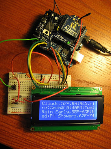
Several months ago I released XBeeArduinoService. Since then I have been working on the next version. It's now available and has a new name: Droplet.

What's New
- Menu/Navigation: The first version relied on a dedicated button for each service. This worked but doesn't scale well since you will quickly run out of buttons. Now it uses a menu to display the available services. Along with the menu are four buttons for navigation: Next, Previous, Select, and Escape.


- Pagination: Previously, each message was limited to 80 characters, which of course is not much. Now messages that exceed 80 characters are formatted into multiple pages. A multi-page message is indicated by an arrow "⇾" character in the bottom right corner. When this character is present, selecting the Next button loads the next page.


- Push Services: these are services that run in the background and send messages (or droplets) to the remote. I have written push services for Twitter, Gmail and Google Calendar. Note: these are different from pull services, which are user initiated and are listed on the menu.
- History: You can now access previous messages that were sent to the LCD. This is helpful if you clicked the Next button too quickly, or you want to see any messages that were sent while you were away (e.g. missed tweets, calendar events). Selecting the Previous button while any message is displayed will load the previous message.
- New Services: Twitter, Twitter Search, Google Calendar, IMAP "Push" Email (e.g Gmail) and Top News.
- Light and Sound: A red LED flashes when a Push Service sends a message (tweets/calendar/email) and optionally a buzzer can sound. The Google Calendar service sounds the buzzer if "#buzzer#" appears in a Google Calendar event description. It effectively becomes a Google alarm clock when using the buzzer option with Google Calendar.
- Multiple Remotes: This version includes better support for multiple remotes. You can use the XBee broadcast address (0x00000000ffff) to send messages to all remotes or target one or more specific remotes.
A Demo
Parts
For this version I added the following parts:
- (1) CEM-1203 Magnetic Buzzer
- (1) LED. Any LED will do
- (1) 100 Ohm Resistor for the LED
- (3) Push Buttons (you'll need a total of four)
Circuit
In an attempt to not repeat myself, in this entry I'm only going to cover what's new, so you'll want to familiarize yourself with the previous version.
Now to wire up the new parts. Connect the buzzer to the Arduino Analog 0 and the negative terminal to GND. Yeah, that's right, Arduino lets you repurpose the Analog pins as Digital outputs. Analog 0-5 can accessed as Digital pins 14-19. Pretty neat, huh? Here's some more info.
Wire the LED to the Arduino Digital 5 pin and GND, placing your resistor in series.
Wire each push button to GND and the following Arduino Pin:
Next: Digital 2
Previous: Analog 1 (We are also repurposing this pin to be Digital, same as the buzzer pin)
Select: Digital 3
Escape: Digital 4
In case you're wondering whether it's safe or even a good practice to connect a button without a pull-up/down resistor, keep reading. In the previous version I was using a pull up resistor to drive the pin to a known state while the button was in its normally-open position. It turns out there's an easier way to do this by using the Arduino's internal pull up resistors. The pull-up resistors are enabled by setting the pin mode to INPUT, then turning them on with a digital write HIGH. In this configuration, the pin will read HIGH until the button is depressed, when it will read LOW, and we don't need to mess with any resistors! Thanks to todbot for this technique.
XBee Configuration
The XBee configuration is identical to the previous version.
Software
Download the project software from Google Code. This download includes everything you need to get it up and running except for Java (requires Java 5) and Eclipse. Eclipse is recommended but isn't required and if you are experienced with Java you can use your IDE of choice or run from the command-line. Being Java, this software will run on a variety of platforms (Windows, Mac, Linux etc.). The only limiting factor is the RXTX serial library and I've included binaries for Windows, Mac and Linux (Arduino uses RXTX also).
As before, you need to install two Arduino libraries. XBee-Arduino for XBee communication and LCD4x20 to display text on the LCD. Unzip the downloaded file and you will find these files in the "Arduino" folder of the project:
LCD4x20-781.zip
xbee-arduino-0.1.2.zipUnzip each file and install in your ARDUINO_HOME/hardware/libraries folder
(where ARDUINO_HOME is the location of Arduino on your system. On my machine it's /Users/andrew/Documents/devsoft/arduino-0016/hardware/libraries)
After installation, you should have XBee and LCD4x20 folders under ARDUINO_HOME/hardware/libraries. Note: the LCD library was updated since the previous version, so if you have the previous version, delete the LCD4x20.o file, to force Arduino to recompile the library.
Now upload the Sketch to the Arduino. The sketch (DropletRemote.pde) is located in "Droplet/Arduino/DropletRemote". But before uploading we need to make one minor change. Find the following line:
XBeeAddress64 addr64 = XBeeAddress64(0x0013a200, 0x403e0f30);
and replace the 64-bit address with the (SH + SL) of your XBee coordinator. See the previous blog entry for info on how to get your SH + SL address. Remember to put the XBee Shield jumpers in the "USB" position to upload the Sketch and return the jumpers to the "XBee" position after a successful upload.
Now for the Service Gateway. As before, create an Eclipse project and point it to the Droplet folder. Refer to the previous version if necessary. There are just a few things to change in the Java file. Open DropletDemo.java in Eclipse. This file is located in "/src/com/rapplogic/droplet/impl/" In this file you'll need to specify the address of the remote XBee for the variable "remoteXBee". Also specify the COM port and baud rate of the XBee coordinator.
Since we are using Google and Twitter, you'll need to specify the login information to access your accounts if you want these services. Open google.credentials and specify your Google/Gmail username and password. Now open twitter.credentials and specify your Twitter username and password.
The demo starts up all available services, but possibly you are not interested in running them all. If this is the case, comment out the services you do not want with the Java comment syntax "//" at the beginning of the line. Note: the weather services requires a zip code, so if you are using these services search for "20175" and replace with your zip code. Save the file.
Ok now we're ready to run it. Power up the Arduino, connect the XBee coordinator to the computer and start the application by selecting "Run" from the "Run" menu. Choose one of the services on the LCD menu and click the Select button and you should see the resulting message on the LCD. Woohoo!
Creating Custom Services
The service API has changed significantly since the last version, making it easier to write your own Droplet services. First you need to decide whether you want to create a Pull Service or Push Service. A Pull Service is listed on the menu and is only activated by a button press on the remote. A Push Service runs in the Java application on a periodic basic and sends messages to the remote.
Pull Services
Adding a Pull Service requires an implementation of the PullService interface. This can be accomplished by creating a class that implements the interface, or for simple services, using an anonymous inner class, as in this example. The PullService interface requires that you implement the execute method:
public IContent execute(Integer serviceId, XBeeResponse response, ServiceContext serviceContext) throws Exception
This method provides the following arguments:
- serviceId: this is the menu position of the service, starting at 0. If you have a single service that supports multiple menu items, you'll need to refer to this variable.
- response: the XBeeResponse received from the Arduino. This is useful if you need to know the remote that sent the request or any of details of the transmission, such as RF strength.
- serviceContext: this object exposes several methods of the Droplet API, the most important method for Pull Services being the format method. This method is acessed by serviceContext.getFormatter().format(String); it takes an arbitrary String, of any length, and formats it for display on a LCD. This method will handle pagination if the String doesn't fit on the LCD. This method also optimizes the String for display on the LCD, according to the PaginationRules class. (see Javadoc for details of all Droplet classes/interfaces).
Within this method you can do whatever you need (send an email, turn on your sprinklers etc.), but the service method must return in a timely manner, specifically 6 seconds, although this is configurable. This method returns an instance of IContent, which really a fancy container of the text to be displayed on the LCD. You can return null but the framework will still send a default message to the remote. Here's an example:
PullService time = new PullService() {
public IContent execute(Integer serviceId, XBeeResponse response, ServiceContext serviceContext) throws Exception {

return serviceContext.getFormatter().format("The current time is " + new Date() + ". You will see this response on your LCD after the service executes. You can even use linefeed characters \n to format the response");
}
};
The last activity is to register your service with the Droplet framework. The first argument of the register method is the position of the item in the menu. The position starts at 0, so the second item in the menu is 1.
droplet.registerPullService(1, time);
Now you will need to add your new service as the second menu item in the Arduino Sketch. After the Sketch has been uploaded you should be able to select the second menu item on the remote and it will activate your service. Note: if you change the number of items in the menu, make sure to update the menuSize variable to the new number.
Push Services
There are three types of Push Services: Realtime, Delayed and Runnable. A Realtime service returns a message to be delivered immediately to the remote. A Delayed service returns a message to be delivered to the remote at some point in the future. And finally, a Runnable service occupies a dedicated thread and runs all the time. The Realtime and Delayed services are further divided into two subtypes: Recurring and OneTime, where Recurring services are invoked periodically, and OneTime services are invoked only once.
To create a Realtime service, you will need to extend the RealTimeAlertPushService and implement either the RecurringService or OneTimeService interface. To simplify things, there is a SimpleRealtimeRecurringPushService class that extends RealTimeAlertPushService and implements RecurringService, along with some default values.
Unlike Pull Services, Push Services need to know the 64-bit address of the remote XBee that should receive the message. Optionally you could specify a broadcast address to send to all remotes. Here's an example of a Push Service that sends a wake up alert every weekday at 6 AM. The service returns an instance of the Alert class. An Alert contains properties for determining whether or not the LED should flash or the buzzer should sound. While Pull Services always return a message to the LCD for display, Push Services may return null, in which case nothing is sent.
XBeeAddress64 remoteXBee = new XBeeAddress64(0x00,0x13,0xa2,0x00,0x40,0x0a,0x3e,0x02);

SimpleRealtimeRecurringPushService wakeUp = new SimpleRealtimeRecurringPushService(remoteXBee) {

@Override
public Alert execute(ServiceContext serviceContext) throws Exception {
 Calendar cal = Calendar.getInstance();

 int dayOfWeek = cal.get(Calendar.DAY_OF_WEEK);

 if (dayOfWeek == Calendar.SATURDAY || dayOfWeek == Calendar.SUNDAY) {
  // it's the weekend.  you can sleep in
  return null;
 }

 int minute = cal.get(Calendar.MINUTE);
 int hour = cal.get(Calendar.HOUR_OF_DAY);

 if (hour == 6 && minute == 0) {
  // wake up!
  Alert alert = new Alert();
  alert.setContent(serviceContext.getFormatter().format("It's Wake Up Time !!!!!!"));
  alert.setRemoteXBeeAddress(this.getRemoteXBeeAddress());
  // flash the LED
  alert.setFlashLed(true);
  // sound the alarm!
  alert.setSoundAlarm(true);

  return alert;
 }

 // not time yet
 return null;
}
};

// run once a minute (delay is in milliseconds, so multiple by 1000)
wakeUp.setDelay(60000);
wakeUp.setName("WakeUp");

// register the service with the framework
droplet.registerPushService(wakeUp);
For more examples, look in the com.rapplogic.droplet.impl.services.* packages for the source code to all services.
What's Next?
- Plug Computer. I recently received a SheevaPlug. SheevaPlug is a low power ARM computer, about the size of a wall adapter, that runs Linux. My goal is to run the Droplet Java application on the SheevaPlug.
- Extra Pins. After everything is wired-up, we still have 6 Arduino pins left: 4 Analog or Digital (Analog 2-5, Digital 16-19) and 2 Digital (12, 13), so you could wire up some dedicated "Radio" buttons, sensors, or even add a second LCD.
- Case. Ok, this thing is a bit ungainly. At some point I'll start working on a case to hide the internals.
- Larger Display. I've been on the lookout for a low cost alternative to the 4x20 LCD, with support for displaying more than 80 characters.
Comments are great but if you have questions please send email instead since I may not see the comments for a few days or a possibly longer. My email can be found from the "view my complete profile" link in the right column.