 This is an Arduino based wireless device that can display arbitrary content (weather, news etc) at the touch of a button, via an XBee radio. Currently it supports weather by zip code and displays on a 4x20 LCD, but it's designed to easily expand to additional services. Some ideas for other services include: calendar events, traffic, next bus/train, tweets, news, mail, adjust thermostat, next track (itunes), turn on/off/dim light etc. This is mostly useful for quick information when you are not close enough to a computer (nightstand, living room, kitchen etc.) I chose weather as the initial service since it's relatively useful and part laziness since my wife asks me for the forecast every morning so she can plan her outfit.
How it Works
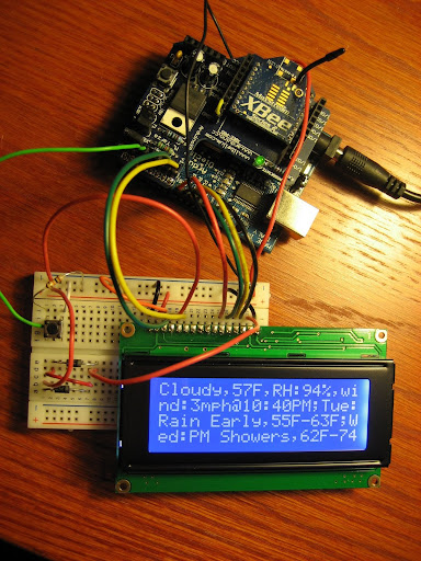
The system consists of a Service Gateway and one or more remote Arduinos. The remote Arduino consists of an XBee radio, LCD, and one or more buttons that are hardwired to a particular service (e.g. weather, news). When the button is pressed, it uses the XBee-Arduino library to send an XBee packet to the Service Gateway and displays the subsequent response on the LCD.
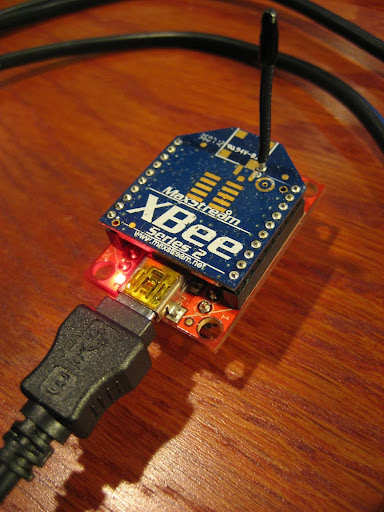
The Service Gateway is an XBee-API application that connects to an XBee Coordinator. The Service Gateway receives the request from the remote XBee and sends back a packet containing character data for display on the LCD. The Service Gateway doesn't need to know anything about the remote Arduino; as long as they have the same Channel and PAN ID, they can communicate.
Parts List
- 4x20 LCD This is a Winstar WH2004 from SureElectronics* but any HD44780 compatible should do fine. (Only $12 shipped!)
- Arduino **
- Arduino XBee Shield
- (2) Series 2 XBees ***
- XBee USB Explorer
- 9V Power Supply (not required but recommended so that you can place your Arduino anywhere you have a power outlet)
- 40-pin Male Header to expose LCD pins
- Breadboard, one or more buttons, two 1N4004 diodes, wires etc
** You can substitute an Arduino for a lower cost variant such as Adafruit's Boardino and corresponding XBee Adapter Kit
*** It's possible to substitute with Series 1 (802.15.4) XBees but this will require some code modifications.
Installation and Setup
The first order of business is to configure the XBees. You should have two series 2 XBee radios, one configured with coordinator firmware and the other with end device firmware. I'm recommend using ZB Pro firmware. ZNet should also work but has a limit of 72 bytes per packet so you won't be able to use the entire 80 characters of the display.
Place your XBee coordinator in the USB Explorer and use X-CTU to apply the following configuration:
Click the "Restore" button to clear out any previous configurations
Set PAN ID to an arbitrary value. The end device must also use this exact value
ID=1AAA
Set the node identifier to an arbitrary string. This serves as a convenient way to identify your devices
NI=COORDINATOR
Set API mode to 2 (escape control bytes)
AP=2
Click the "Write" button to save the configuration
Be sure to take note of the Serial High (SH) and Serial Low (SL) values as you will need this later
Now place your XBee end device in the USB Explorer and configure. If you are using ZB Pro firmware, this firmware does not support a disabled sleep option, so you need to perform a trick to keep the end device awake. See this blog entry for details. The end device configuration is identical to the coordinator except for the node identifier:
Click the "Restore" button
Set PAN ID to the same value as the coordinator
ID=1AAA
Set the node identifier to an arbitrary string.
NI=ARDUINOXBEE
Set API mode to 2 (escape control bytes)
AP=2
Click the "Write" button to save the configuration
Wire It Up
Now we're going to wire up the Arduino. Attach your Arduino XBee Shield to your Arduino and place your end device XBee in the shield.
Connect your LCD to a breadboard and wire to Arduino. I wired it up as follows but you can use any digital pins (except 13). This only requires 6 Arduino pins in 4-bit mode, woot! Here's the Winstar WH2004 LCD schematic for reference:
Pin 1 (VSS) - 5V
Pin 2 (Vdd) - GND
Pin 3 (Contrast) - GND
Pin 4 (RS) - Arduino Digital 6
Pin 5 (Read/Write) - GND
Pin 6 (Enable) - Arduino Digital 7
Pin 7 (Data Bus 0) - Arduino Digital 8
Pin 8 (Data Bus 1) - Arduino Digital 9
Pin 9 (Data Bus 2) - Arduino Digital 10
Pin 10 (Data Bus 3) - Arduino Digital 11
Pin 15 (Backlight Power)- 4.2V*
Pin 16 (Backlight Ground) - GND
All pins not listed should be left unconnected
* Now you might be wondering what to do about 4.2V when Arduino is 5V, I was. I found a nifty solution on the Arduino forum that involves a couple 1N4004 diodes to drop voltage close to 4.2. Each 1N4004 has a drop of around 0.7V. I probably could have used one but I ended up using two so I wouldn't go over the 4.2V. With two diodes I'm measuring 3.5V but this seems to work just fine. An LED should also work in place of a 1N4004.
Now connect a pushbutton input so that it provides 0V when depressed and of course 5V when open. Here's a great tutorial on Arduino and buttons.
Ok, so now we have everything wired up and it's time to load the software.
Software
We are using two Arduino libraries: XBee-Arduino and LCD4x20. The XBee-Arduino library provides XBee packet communication, allowing us to send requests for data and display responses on the LCD. The LCD4x20 Arduino Library is based on LCD4Bit but contains modifications to work specifically for a 4x20 HD44780 LCD. The problem with this particular LCD is that line 1 wraps to line 3, line 3 to line 2 and line 2 to line 4; this library corrects this problem and adds some additional features. Because this LCD doesn't shift character data properly, the library maintains a 80 byte buffer in order to perform shifts (e.g. line feed) by rewriting the character data to the display.
Download XBee-Arduino xbee-arduino-0.1.2.zip
Unzip and install in
ARDUINO_HOME/hardware/libraries
Download the LCD4x20 library and similarly install in
ARDUINO_HOME/hardware/libraries
Download the Service Gateway and Arduino Sketch for this project and unzip.
We're going to need to make a few changes to the Arduino Sketch. Open the Arduino sketch (in XBeeArduinoService/Arduino/XBeeArduinoLcd) and find the lines, starting with "rsPin" and specify the Arduino digital pin for each corresponding LCD pin. You don't need to change anything if you wired it according to my suggestions.
Now replace the 64-bit address on the following line with the (SH + SL) of your XBee coordinator. You copied it down, right?
XBeeAddress64 addr64 = XBeeAddress64(0x0013a200, 0x403e0f30);
Save the Sketch.
Upload the Sketch
While the Arduino is unpowered, set the USB/XBee jumpers on the Arduino XBee Shield to the USB position (this directs the Arduino's serial port to USB so we can upload). Connect the Arduino to your computer and upload the Sketch. Note: you may see a few warnings in red font -- this is ok. If successful, your LCD will be displaying a message: "XBeeArduinoLcd v1.0...".
Unplug the Arduino and return jumpers in the XBee position. Now you can power your Arduino externally and place anywhere within XBee range of your computer!
Now for the Service Gateway setup
Service Gateway
Download "Eclipse IDE for Java" for your platform from Eclipse and install (this usually involves only unzipping it).
Start Eclipse and select Import from the File menu. Expand the General folder and select "Existing Projects into Workspace".
Select File->New->Java Project
Give the project a name, maybe "XBeeArduinoService"
Check the "create project from existing source" radio button
Browse to the location where you unzipped the project and select the "XBeeArduinoService" folder
Hit "Finish"
It should automatically find the libraries and be ready to go.
In the left window, expand the project, the "src" folder and the "com.rapplogic.xbeearduinoservice" package. Now open XBeeArduinoWeatherService.java. We will need to update a few variables. At the top of the file, find the comPort variable and replace with the COM port of the USB Explorer. For Windows users, you can find the COM port by going to Start->(right-click)My Computer->Manage, then Select Device Manager and Ports. It should appear as USB Serial Port. For Mac users it will appear under /dev/tty.usbserial*, so an ls -l dev/tty.usbserial (tab tab) before and after the device is plugged in should tell you the com port.
The last change is to enter the zip code for your local weather:
Weather weather = getWeather("97007", true);Save it. (Eclipse compiles it automatically)Place your XBee coordinator in the USB Explorer and connect to your computer.
Now we need to create a Run Configuration:
Select "Run Configurations..." from the "Run" menu
Select "Java Application"
Press the "new" button icon
It should automatically find "com.rapplogic.xbeearduinoservice.XBeeArduinoWeatherService"
Click Run. Now that the service is running, press the Arduino button and get your weather!
Top stop the service, press the red square button. Now to start it again you only need to select "Run" from the "Run" menu.
Creating your own Services
To add another service you will need to wire a second push button to an available digital input on the Arduino. Then define the service with a unique number at the top of the Sketch, for example:
define ITUNES_NEXT_TRACK 2
Create a variable that holds the button's digital input:
int itunesButton = 3;
At the bottom of the file add a if statement to detect if the button was pressed:
if (digitalRead(itunesButton) == LOW) {
requestService(ITUNES_NEXT_TRACK);
}
For the Service Gateway, you'll need to write the code that implements the service and returns a String to be displayed on the LCD. Open the XBeeArduinoWeatherService.java (or create your own class) and add a call to your service method in processRequest method, like so:
protected String processRequest(int requestType) throws Exception {
switch (requestType) {
case 1:
// weather
Weather weather = getWeather("97007", true);
return weather.toString();
case 2: // matches the service id (ITUNES_NEXT_TRACK) in the Sketch
// itunes next track
return this.changeItunesTrackAndReturnSongInfo();
}
}
where you have defined a methodString changeItunesTrackAndReturnSongInfo() {
// changes the itunes track and returns the current song for display
...
}
The service will truncate the response to 80 characters since that is the size of the display.
The processRequest method must respond within getServiceTimeoutMillis() milliseconds (defaults to 6000 or 6 seconds) or it will timeout and send the "Application Timeout" message to LCD. You can change this timeout by calling setServiceTimeoutMillis method. However, if you change this timeout, you should also change the Arduino timeout (APPLICATION_TIMEOUT) to the same value, plus a buffer of 1 or 2 seconds. The buffer is necessary to account for the round trip packet transmission time. Packets are usually delivered in under 100ms but packet size, distance, interference, and all sorts of factors can result in delays.
Adding another remote Arduino is easy and requires no modifications to the Service Gateway. Just configure the remote Arduino with the same PAN ID (ID) and it will automatically join the network. You can add up to eight with a single coordinator and to scale beyond that you would just need to introduce a router.
What's Next?
Here are some ideas for phase 2:
- "Continue" feature to handle messages larger than 80 characters (LCD screen size)
- LCD menu system for accessing more services than we have available digital inputs
- Low power remote. Without the LCD backlight, and by putting the XBee in sleep mode, the remote Arduno could be powered by batteries, making it much more mobile
- Alert framework. Alerts are initiated by the Java service and displayed on the LCD. An example might be a twitter tweet or meeting reminder. Alerts would initiate a LED blinking routine to capture ones attention.
- Low power device such as the BeagleBoard to replace a PC as the service gateway. I don't like the idea of leaving a computer on all the time as it wastes electricity. Right now I'm using an old notebook that doesn't use much power.
- A nice looking enclosure


