Saturday, November 21, 2009

Chatduino: An AIM Client for Arduino/Wiznet 5100

This is an AIM instant messenger client for Arduino/Wiznet 5100, which allows you to communicate with your Arduino project from anywhere on the internet, in near real-time. You can communicate with your project through any AIM client or even your cell phone by using text messaging with Mobile AIM, and since communication is channeled though the AIM server, both the Arduino+Wiznet and chat client can exist behind firewalls.


At first I looked into creating an Arduino library for XMPP/Jabber. This would allow you to connect to Google Talk/App Engine or any other XMPP service. The problem which this approach is most XMPP services require TLS for security, and TLS isn't going to happen on an ATmega328 (thinly veiled challenge going out to anyone who can prove otherwise). I looked at a few other chat services and finally settled on AOL instant messenger (AIM) because it's very popular and the protocol (TOC) is easy to implement on the Arduino. Although the protocol is proprietary, it is well understood and there are many open source libraries/apps available.

Hardware

Arduino + Wiznet W5100 Ethernet chip. This comes packaged together nicely with the Arduino Ethernet Shield. See below for parts.

Installation and Setup

If you don't already have an AIM account, go to http://www.aim.com/ and register for a free screen name.

Download Chatduino and open in Arduino

The official Arduino ethernet library does not support DHCP. Because of this we need to specify the IP address of the Wiznet. For example:
static byte ip[] = { 192, 168, 1, 99 };
Choose an IP address that is not in use and one that is not used by DHCP. I chose 192.168.1.99 since my router (Linksys) uses 192.168.1.100 and up for DHCP.

The Arduino ethernet library also does not support DNS, so we need to use the IP address of the AIM server. I have provided the two IP addresses for the TOC domain (toc.oscar.aol.com) at this time. Either should work but these could change over time. If you are having connection problems you may need to do a domain lookup on toc.oscar.aol.com to get the new IP addresses.
//static byte server[] = { 64, 12, 202, 14 };
static byte server[] = { 64, 12, 202, 7 };
The default port of the AIM server is 5190. If you are having connectivity issues, it's possible that your network is blocking this port. Try using port 80 instead.

Update: Some users have suggested an alternate Ethernet library that supports both DNS and DHCP. You might want to give this a try.

Scroll down toward the bottom of the sketch and specify your screen name and password:
char screenName[] = "yourscreenanme";
char pass[] = "yourpassword";
Specify the length of the message array. You will still be able to receive messages that are larger but of course only "msgLen" of the message will be stored in the array. Remember that the ATmega has limited memory (1K), so you don't want to make the arrays excessively large.
const uint16_t msgLen = 50;
Specify the length of the "from" screen name. This value should be at least (+1) larger than the largest screen name you expect.
const uint16_t fromLen = 18;
Now add your code inside the if (readMessage(from, fromLen, msg, msgLen) == 0) { block. This statement evaluates to true whenever a message is received.

The from string contains the screen name that sent the message and the msg string contains the message. For example:
if (strcmp(from, "myscreenname") == 0) {
// a message from "myscreenname"
if (strcmp(msg, "get temp") == 0) {
// return analog reading of temp sensor
itoa(analogRead(0), msg, 10);
sendMessage(from, msg);
}
else if (strcmp(msg, "turn on led") == 0) {
// turn on led
digitalWrite(ledPin, HIGH);
sendMessage(from, "ok");
}
}
Because of the bi-directional nature of chat, it's also possible to send messages based on external events. Here's an example:
//Place outside of readMessage block
if (digitalRead(motionPin) == HIGH) {
sendMessage("anyscreenname", "motion detected!");
}
Now you should be able to upload your Sketch and it should sign-on to AIM.

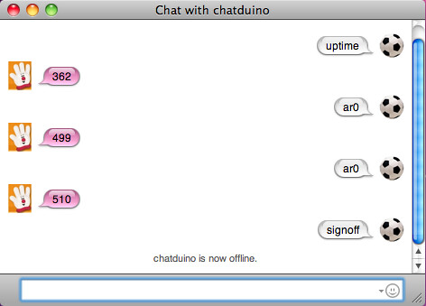
I have provided a few functions that you may find useful. The processPinRequest function provides I/O pin control. For example ar5 returns an analogRead of pin 5, and dw4=1 performs a digitalWrite(4, HIGH). Analog write (PWM) and digital read are also supported. It's recommend that you restrict write operations to verified screen names. To accomplish this, you can set authUser to a specific screen name that is allowed to manipulate the I/O pins. By default all users are allowed to perform pin readings. Refer to the function comments for more information.

It is highly recommended to sign-off from AIM before uploading a new sketch or powering off the unit, or AIM gets confused and may not allow reconnects for a period of time. You can sign-off by sending a "signoff" message. I've encountered a few instances where the Sketch failed to connect to AIM after it was previously connected and signed off. Hitting the reset button a few times seems to fix this issue (wait at least 15 seconds between resets).

The Sketch will automatically attempt to reconnect if disconnected from AIM. You can send the "reconnects" message to get the number of reconnects. I've been running the service for over a week with zero reconnects.

Serial debug can be turned on by setting #define CHATDUINO_DEBUG to 1 at the top of the sketch.

Note: I am using the Wiznet module (WIZ812MJ) directly, without a shield. This means I need to explicitly reset the device on startup. This is done by connecting the Wiznet reset pin to 9 (use a resistor, 1K or so), and setting #define WIZNET812MJ (top of sketch) to 1. The Arduino Ethernet Shield will reset automatically and does not require this step.

Parts

Seeedstudio currently has the best price on the Arduino Ethernet Shield ($29), although they are out of stock at the time of this writing. This is actually a clone but is functionally equivalent to the official shield.

NKC Electronics sells the official Arduino Ethernet Shield for $40 or you can get their version for $32 (requires assembly).

Whatever you choose, make sure you get a Wiznet based device and not Microchip's ENC28J60.

If you're looking for the most cost effective solution (less then the cost of the ethernet shield alone), and you don't mind wiring it together, I recommend an Arduino clone, such as Modern Device's RBBB (~$12) and the WIZNET812MJ (~$21). This setup requires a breadboard/protoboard, 3.3V power, some female/male jumpers, and a USB-serial device to program the RBBB.

Considerations

Currently the sketch only processes incoming messages. Other commands: CONFIG2, UPDATE_BUDDY2, PING etc. are ignored. In a future release I would like to support buddy list updates, which would allow you to receive notifications when your friends signon/signoff.
Other improvements may include using EEPROM to save memory and not blocking on readMessage if the receive buffer is empty. Of course at this time it's just a sketch but if people find it useful, I may release it as an Arduino library.
Saturday, September 12, 2009

Droplet on the SheevaPlug


Droplet requires a Java service to listen for requests from remote Droplets and run background threads for push services. At first I used my notebook to run the service, but it wasn't very convenient since it tended to not stay put, or powered on for very long. Around this time I received a SheevaPlug, after a 1.5 month wait. The SheevaPlug is a low power, compact, ARM based Linux computer and is perfect for running the Droplet service. In this blog entry I describe how to get the Droplet service running on the SheevaPlug.

Setup

If you are using a FTDI usb-serial device to interface with XBee (e.g. XBee Explorer USB), you'll need to upgrade the kernel since the kernel shipped with the plug does not have usb-serial driver support. (Arduino uses the same FTDI usb-serial chip). Fortunately, for those of us not comfortable with compiling Linux, there are prebuilt kernels available with usb-serial support. Here's the wiki entry that describes the installation process.

The SheevaPlug only has 512MB of disk space, so you can quickly run out of disk space after installing a few packages (Java itself requires over 300MB). The solution to this problem is to install an SD card as your primary file system. This step is optional but strongly recommended for the reason that in addition to more disk space, the plug will also run quite a bit faster. Here's a guide that explains how to add an SD card.

Since this is an ARM computer and not x86, we can't simply install Sun's version of Java for Linux. Fortunately Sun open-sourced Java several years ago and the folks at Sun and RedHat have been hard at work on OpenJDK, rewriting the proprietary parts and porting it to additional architectures (ARM, MIPS, PowerPC etc).

Install OpenJDK

apt-get install openjdk-6-jdk
Install RXTX. RXTX provides serial port communications for Java applications

apt-get --no-install-recommends install librxtx-java
Now we are ready to install Droplet.

Make a folder for the application. I'm using "/root/apps/droplet". Zip up your Eclipse project, transfer it to the plug and unzip in the new folder.

Since we don't have Eclipse on the plug, we need a script to start the application. Create the following script and in a file called droplet.sh

#!/bin/bash

# application entry point
MAIN_CLASS=com.rapplogic.droplet.impl.DropletDemo

# specify path to the rxtx jar.  default is for librxtx-java
RXTX_JAR=/usr/share/java/RXTXcomm.jar

# location of rxtx modules when installed with apt-get
RXTX_LIB_PATH=/usr/lib

# FTDI should appear as /dev/ttyUSB0 if this is the only USB device
COM_PORT=/dev/ttyUSB0

# build classpath
JAR_LIST=`find lib -name '*.jar'`

# add all jar libraries to classpath
for file in $JAR_LIST
do
#echo "adding $file to classpath"
CLASSPATH=$CLASSPATH:$file
done

# append droplet compiled classes (bin) and rxtx jar to classpath
CLASSPATH=$CLASSPATH:bin:$RXTX_JAR

# start Java with a 16MB heap, using the Cacao JIT compiler
java -cacao -Xms16m -Xmx64m -classpath $CLASSPATH -Djava.library.path=$RXTX_LIB_PATH $MAIN_CLASS $COM_PORT 2> droplet.err 1> /dev/null
Make the script executable:

chmod u+x droplet.sh
Note: I'm running the application as root. This probably isn't a good practice but the plug is running inside my firewall, with no ports open to the public, so I think it's fine.

Since we installed RXTX with the lib-rxtx package, we want to remove the RXTX Java library from the project so we don't have multiple RXTX libraries in the classpath.

rm lib/RXTXcomm.jar
And for good measure remove the RXTX native Linux library.

rm librxtxSerial.so
You should now be able to to start Droplet:

./droplet.sh
Check the log if things aren't working as expected (log file is ./logs/droplet.log). Go ahead an kill the app (Ctrl-c).

We are not quite done yet. To have the application start whenever the SheevaPlug boots, we need to add a startup hook. But first we'll need to create another script to start the application in the background. Save this script as droplet-nohup.sh

#!/bin/bash

cd /root/apps/droplet/
nohup ./droplet &
Make it executable

chmod u+x droplet-nohup.sh
To add the startup hook, insert a call to the droplet-nohup.sh script at the end of the "do_start" function in /etc/init.d/bootmisc.sh

# startup droplet
sudo /root/apps/droplet/droplet-nohup.sh
Now reboot the plug and it should automatically start Droplet.

Performance

The performance of OpenJDK Java on the plug is not great but mostly sufficient. I had to rewrite the Twitter service, replacing XPath with StAX because the XPath implementation was consistently timing out. It was taking 20 seconds or more just to parse the friends's timeline! In comparison, the StAX implementation completes in about 5 seconds. In hindsight I could have used JSON, which is quite fast and is already used for Twitter search.

One possible explanation for the slow performance is the lack of Hotspot in OpenJDK. A significant portion of Hotspot was written in assembly, making it very difficult to port. The IcedTea project has been working to address this gap, first with Zero and now with Shark, which is based on LLVM. See this article for more information.

What Else?

I've been running Droplet on the SheevaPlug for the last couple weeks. Overall I've been quite pleased although there is one issue that has popped up a few times. For no apparent reason the Twitter service thread will block indefinitely on what appears to be the HTTP call. When this occurs the rest of the app continues to function but you won't see new Tweets. If you encounter this issue just restart the app.

You may need to adjust the timeout if you are getting "Application Timeout" messages. Usually this will only occur for the Twitter services. This is a two step process. First open the Arduino Sketch and adjust the following line:

#define APPLICATION_TIMEOUT 7500
Then open Droplet.java and adjust the timeout:

private long serviceTimeoutMillis = 6000. 
The Arduino timeout will always need to be about 1.5 seconds longer than the Java timeout to account for the packet roundtrip transmission time. Unless you have installed the Java compiler on the plug, you'll need to make this change in Eclipse, then copy the "bin" folder to the plug.

Now that you are using the only USB port, if you need additional ports you can add a USB hub. I've found that the Belkin F5U407 USB hub works great with the SheevaPlug. Keep in mind you should not be drawing much power from the USB hub, unless you are using a powered hub.

Conclusion

So now you have an always on Droplet service! Place your plug at the back of your desk, or anywhere you have an ethernet connection and forget about it. You should be able to place Droplet remotes anywhere, within range, and they will just work. Of course since the SheevaPlug is a general purpose Linux computer, you can use for other purposes, web server, file server etc.

Update: I installed a 90 day evaluation of Sun's Java SE for Embedded and the performance is now significantly improved. They have several different versions but the one that's compatible with the SheevaPlug is Java SE for Embedded 6.0 Update 10 ARMv5 Linux Early Access, EABI, glibc 2.5, Soft Float, Little Endian (Headless or Headful). Now I just need to figure out how to purchase the full version, as there is no hint on their site of how to do so.

Friday, August 7, 2009

Droplet

Several months ago I released XBeeArduinoService. Since then I have been working on the next version. It's now available and has a new name: Droplet.

What's New
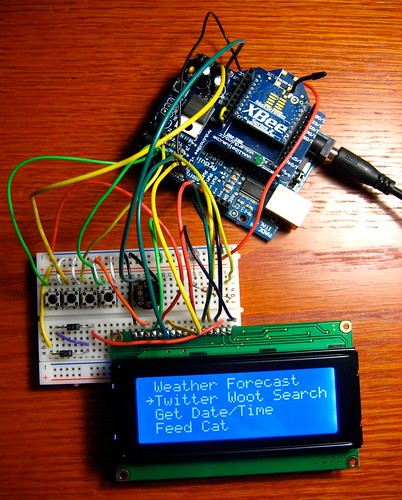
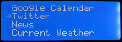
  • Menu/Navigation: The first version relied on a dedicated button for each service. This worked but doesn't scale well since you will quickly run out of buttons. Now it uses a menu to display the available services. Along with the menu are four buttons for navigation: Next, Previous, Select, and Escape.


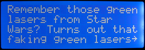
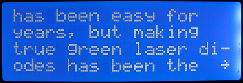
  • Pagination: Previously, each message was limited to 80 characters, which of course is not much. Now messages that exceed 80 characters are formatted into multiple pages. A multi-page message is indicated by an arrow "⇾" character in the bottom right corner. When this character is present, selecting the Next button loads the next page.

  • Push Services: these are services that run in the background and send messages (or droplets) to the remote. I have written push services for Twitter, Gmail and Google Calendar. Note: these are different from pull services, which are user initiated and are listed on the menu.
  • History: You can now access previous messages that were sent to the LCD. This is helpful if you clicked the Next button too quickly, or you want to see any messages that were sent while you were away (e.g. missed tweets, calendar events). Selecting the Previous button while any message is displayed will load the previous message.
  • New Services: Twitter, Twitter Search, Google Calendar, IMAP "Push" Email (e.g Gmail) and Top News.
  • Light and Sound: A red LED flashes when a Push Service sends a message (tweets/calendar/email) and optionally a buzzer can sound. The Google Calendar service sounds the buzzer if "#buzzer#" appears in a Google Calendar event description. It effectively becomes a Google alarm clock when using the buzzer option with Google Calendar.
  • Multiple Remotes: This version includes better support for multiple remotes. You can use the XBee broadcast address (0x00000000ffff) to send messages to all remotes or target one or more specific remotes.
A Demo

Parts

For this version I added the following parts:
Circuit

In an attempt to not repeat myself, in this entry I'm only going to cover what's new, so you'll want to familiarize yourself with the previous version.

Now to wire up the new parts. Connect the buzzer to the Arduino Analog 0 and the negative terminal to GND. Yeah, that's right, Arduino lets you repurpose the Analog pins as Digital outputs. Analog 0-5 can accessed as Digital pins 14-19. Pretty neat, huh? Here's some more info.

Wire the LED to the Arduino Digital 5 pin and GND, placing your resistor in series.

Wire each push button to GND and the following Arduino Pin:

Next: Digital 2
Previous: Analog 1 (We are also repurposing this pin to be Digital, same as the buzzer pin)
Select: Digital 3
Escape: Digital 4

In case you're wondering whether it's safe or even a good practice to connect a button without a pull-up/down resistor, keep reading. In the previous version I was using a pull up resistor to drive the pin to a known state while the button was in its normally-open position. It turns out there's an easier way to do this by using the Arduino's internal pull up resistors. The pull-up resistors are enabled by setting the pin mode to INPUT, then turning them on with a digital write HIGH. In this configuration, the pin will read HIGH until the button is depressed, when it will read LOW, and we don't need to mess with any resistors! Thanks to todbot for this technique.

XBee Configuration

The XBee configuration is identical to the previous version.

Software

Download the project software from Google Code. This download includes everything you need to get it up and running except for Java (requires Java 5) and Eclipse. Eclipse is recommended but isn't required and if you are experienced with Java you can use your IDE of choice or run from the command-line. Being Java, this software will run on a variety of platforms (Windows, Mac, Linux etc.). The only limiting factor is the RXTX serial library and I've included binaries for Windows, Mac and Linux (Arduino uses RXTX also).

As before, you need to install two Arduino libraries. XBee-Arduino for XBee communication and LCD4x20 to display text on the LCD. Unzip the downloaded file and you will find these files in the "Arduino" folder of the project:

LCD4x20-781.zip
xbee-arduino-0.1.2.zip

Unzip each file and install in your ARDUINO_HOME/hardware/libraries folder
(where ARDUINO_HOME is the location of Arduino on your system. On my machine it's /Users/andrew/Documents/devsoft/arduino-0016/hardware/libraries)

After installation, you should have XBee and LCD4x20 folders under ARDUINO_HOME/hardware/libraries. Note: the LCD library was updated since the previous version, so if you have the previous version, delete the LCD4x20.o file, to force Arduino to recompile the library.

Now upload the Sketch to the Arduino. The sketch (DropletRemote.pde) is located in "Droplet/Arduino/DropletRemote". But before uploading we need to make one minor change. Find the following line:

XBeeAddress64 addr64 = XBeeAddress64(0x0013a200, 0x403e0f30);

and replace the 64-bit address with the (SH + SL) of your XBee coordinator. See the previous blog entry for info on how to get your SH + SL address. Remember to put the XBee Shield jumpers in the "USB" position to upload the Sketch and return the jumpers to the "XBee" position after a successful upload.

Now for the Service Gateway. As before, create an Eclipse project and point it to the Droplet folder. Refer to the previous version if necessary. There are just a few things to change in the Java file. Open DropletDemo.java in Eclipse. This file is located in "/src/com/rapplogic/droplet/impl/" In this file you'll need to specify the address of the remote XBee for the variable "remoteXBee". Also specify the COM port and baud rate of the XBee coordinator.

Since we are using Google and Twitter, you'll need to specify the login information to access your accounts if you want these services. Open google.credentials and specify your Google/Gmail username and password. Now open twitter.credentials and specify your Twitter username and password.

The demo starts up all available services, but possibly you are not interested in running them all. If this is the case, comment out the services you do not want with the Java comment syntax "//" at the beginning of the line. Note: the weather services requires a zip code, so if you are using these services search for "20175" and replace with your zip code. Save the file.

Ok now we're ready to run it. Power up the Arduino, connect the XBee coordinator to the computer and start the application by selecting "Run" from the "Run" menu. Choose one of the services on the LCD menu and click the Select button and you should see the resulting message on the LCD. Woohoo!

Creating Custom Services

The service API has changed significantly since the last version, making it easier to write your own Droplet services. First you need to decide whether you want to create a Pull Service or Push Service. A Pull Service is listed on the menu and is only activated by a button press on the remote. A Push Service runs in the Java application on a periodic basic and sends messages to the remote.

Pull Services

Adding a Pull Service requires an implementation of the PullService interface. This can be accomplished by creating a class that implements the interface, or for simple services, using an anonymous inner class, as in this example. The PullService interface requires that you implement the execute method:

public IContent execute(Integer serviceId, XBeeResponse response, ServiceContext serviceContext) throws Exception

This method provides the following arguments:
  • serviceId: this is the menu position of the service, starting at 0. If you have a single service that supports multiple menu items, you'll need to refer to this variable.
  • response: the XBeeResponse received from the Arduino. This is useful if you need to know the remote that sent the request or any of details of the transmission, such as RF strength.
  • serviceContext: this object exposes several methods of the Droplet API, the most important method for Pull Services being the format method. This method is acessed by serviceContext.getFormatter().format(String); it takes an arbitrary String, of any length, and formats it for display on a LCD. This method will handle pagination if the String doesn't fit on the LCD. This method also optimizes the String for display on the LCD, according to the PaginationRules class. (see Javadoc for details of all Droplet classes/interfaces).
Within this method you can do whatever you need (send an email, turn on your sprinklers etc.), but the service method must return in a timely manner, specifically 6 seconds, although this is configurable. This method returns an instance of IContent, which really a fancy container of the text to be displayed on the LCD. You can return null but the framework will still send a default message to the remote. Here's an example:
PullService time = new PullService() {
public IContent execute(Integer serviceId, XBeeResponse response, ServiceContext serviceContext) throws Exception {

return serviceContext.getFormatter().format("The current time is " + new Date() + ". You will see this response on your LCD after the service executes. You can even use linefeed characters \n to format the response");
}
};
The last activity is to register your service with the Droplet framework. The first argument of the register method is the position of the item in the menu. The position starts at 0, so the second item in the menu is 1.
droplet.registerPullService(1, time);
Now you will need to add your new service as the second menu item in the Arduino Sketch. After the Sketch has been uploaded you should be able to select the second menu item on the remote and it will activate your service. Note: if you change the number of items in the menu, make sure to update the menuSize variable to the new number.

Push Services

There are three types of Push Services: Realtime, Delayed and Runnable. A Realtime service returns a message to be delivered immediately to the remote. A Delayed service returns a message to be delivered to the remote at some point in the future. And finally, a Runnable service occupies a dedicated thread and runs all the time. The Realtime and Delayed services are further divided into two subtypes: Recurring and OneTime, where Recurring services are invoked periodically, and OneTime services are invoked only once.

To create a Realtime service, you will need to extend the RealTimeAlertPushService and implement either the RecurringService or OneTimeService interface. To simplify things, there is a SimpleRealtimeRecurringPushService class that extends RealTimeAlertPushService and implements RecurringService, along with some default values.

Unlike Pull Services, Push Services need to know the 64-bit address of the remote XBee that should receive the message. Optionally you could specify a broadcast address to send to all remotes. Here's an example of a Push Service that sends a wake up alert every weekday at 6 AM. The service returns an instance of the Alert class. An Alert contains properties for determining whether or not the LED should flash or the buzzer should sound. While Pull Services always return a message to the LCD for display, Push Services may return null, in which case nothing is sent.
XBeeAddress64 remoteXBee = new XBeeAddress64(0x00,0x13,0xa2,0x00,0x40,0x0a,0x3e,0x02);

SimpleRealtimeRecurringPushService wakeUp = new SimpleRealtimeRecurringPushService(remoteXBee) {

@Override
public Alert execute(ServiceContext serviceContext) throws Exception {
Calendar cal = Calendar.getInstance();

int dayOfWeek = cal.get(Calendar.DAY_OF_WEEK);

if (dayOfWeek == Calendar.SATURDAY || dayOfWeek == Calendar.SUNDAY) {
// it's the weekend. you can sleep in
return null;
}

int minute = cal.get(Calendar.MINUTE);
int hour = cal.get(Calendar.HOUR_OF_DAY);

if (hour == 6 && minute == 0) {
// wake up!
Alert alert = new Alert();
alert.setContent(serviceContext.getFormatter().format("It's Wake Up Time !!!!!!"));
alert.setRemoteXBeeAddress(this.getRemoteXBeeAddress());
// flash the LED
alert.setFlashLed(true);
// sound the alarm!
alert.setSoundAlarm(true);

return alert;
}

// not time yet
return null;
}
};

// run once a minute (delay is in milliseconds, so multiple by 1000)
wakeUp.setDelay(60000);
wakeUp.setName("WakeUp");

// register the service with the framework
droplet.registerPushService(wakeUp);
For more examples, look in the com.rapplogic.droplet.impl.services.* packages for the source code to all services.

What's Next?
  • Plug Computer. I recently received a SheevaPlug. SheevaPlug is a low power ARM computer, about the size of a wall adapter, that runs Linux. My goal is to run the Droplet Java application on the SheevaPlug.
  • Extra Pins. After everything is wired-up, we still have 6 Arduino pins left: 4 Analog or Digital (Analog 2-5, Digital 16-19) and 2 Digital (12, 13), so you could wire up some dedicated "Radio" buttons, sensors, or even add a second LCD.
  • Case. Ok, this thing is a bit ungainly. At some point I'll start working on a case to hide the internals.
  • Larger Display. I've been on the lookout for a low cost alternative to the 4x20 LCD, with support for displaying more than 80 characters.

Comments are great but if you have questions please send email instead since I may not see the comments for a few days or a possibly longer. My email can be found from the "view my complete profile" link in the right column.

Monday, June 22, 2009

Google Talk XBee Motion Detector


I bought a PIR motion detector from SparkFun a while back. I played around with it a bit, and it works great (at 9V, not 5V), but being hardwired had its limitations. So recently I started a project to make the motion detector wireless, with an XBee radio, and send motion events over Google Talk. This allows you to easily monitor motion events while at work or away.

As for ideas on what to use it for: you could aim the PIR at your couch and see if your pets are violating the couch policy, get notified when your wife/kids get home, place by your front door and find out when a package arrives etc.


This solution uses the XBee I/O Line monitoring feature to send motion detection events to the XBee coordinator. The change detection feature is used to send an I/O sample whenever the PIR alarm pin goes low. With this configuration, the PIR alarm pin is connected directly to an XBee digital input pin, not requiring a micro-controller.

A Java class (XBeeMotion) uses XBee-API to receive motion events and send them to Google Talk. The Google Talk communication is provided by XBee-XMPP, which depends on the Smack library for XMPP.

Ingredients
XBee Configuration

This software works for both Series 1 and 2 XBees. For Series 2 you will need to load the API Coordinator and End Device firmware, if you don't already have it installed. Series 1 is nice in that one firmware image supports both AT and API mode and Coordinator/End Device.

Coordinator Configuration

Series 2 XBees only: place one of the XBees in the XBee Explorer and use X-CTU to flash the ZB Pro API Coordinator Firmware (version 2141 at this time).

Now apply the following configuration (both series, except where noted). Digi did a nice job providing a consistent command set across Series 1 and 2 XBees.


Click the "Restore" button to clear out any previous configurations.
You can skip this step if you just flashed the firmware. Note: for series 1,
this will change the API (AP) mode to 0 (disabled), so you will need to go back to
the "PC Settings" tab and uncheck the "Enable API" checkbox. Then, after you set AP=2
and click "Write", you'll need to re-enable this setting.

Set PAN ID to an arbitrary value. The End Device must also use this exact value
ID=1AAA

Set the node identifier to an arbitrary string.
This serves as a convenient way to identify your devices
NI=COORDINATOR

Series 1 Only. Make this the Coordinator
CE=1

Series 1 Only. Set the 16-bit XBee Address to any value
MY=1234

Set API mode to 2 (escape control bytes)
AP=2

Click the "Write" button to save the configuration


End Device Configuration

Series 2 Only: place the other XBee in the XBee Explorer and apply the ZB Pro API End Device Firmware (version 2941)


Click the "Restore" button to clear out any previous configurations

Set PAN ID to an arbitrary value. The End Device must also use this exact value
ID=1AAA

Set the node identifier to an arbitrary string. This serves as a convenient way to identify your devices
NI=MOTION

Series 1 Only. Make this an End Device
CE=0

Series 1 Only. Set the Destination Low Address to the Coordinator
DL=1234

Series 1 Only. Set the 16-bit XBee Address to any value
MY=5678

Set API mode to 2 (escape control bytes)
AP=2

Set DIO4 as A digital input
D4=3

Turn on change detection for DIO4 (bit 4 -> 16 = 0x10)
IC=10

Since we reset the XBee to the factory default, the internal pull-up resistors (PR) are on. The internal pull-up will drive the pin high when left floating

Series 2 Only. Set the Sleep mode to Pin Hibernate. You will need to ground pin 9 to keep the XBee awake
SM=1

Click the "Write" button to save the configuration


The PIR

I know the SparkFun site says the motion detector works at 5V, but trust me it does not. It may seem like it's working but it will fire erratically at times. My guess is that it would be stable at 6 volts or more but I know it works at 9V. According to the SparkFun product description, the PIR can be powered at 3.3V by soldering a jumper. This would be ideal however I have not tested this.

Google Talk

You will need two Google accounts, one for sending and one for receiving. Note: if you have a Google Apps domain, you can create additional user accounts through the administration tool.

Software Installation

Download the software from Google Code, unzip and create an Eclipse project

Open xbee-motion.properties

Enter your Google username/password. Notice the username must include "@gmail.com", unless you have a Google Apps account in which case it must include "@yourdomain.com"

gtalk-username=yourusername@gmail.com
gtalk-password=yourpassword

Specify the Google Talk user(s) to that will receive motion event messages.
You may enter one or more (comma separated list) GTalk users

gtalk-recipient=yourothergmailusername@gmail.com

Specify the COM port of the local XBee (Coordinator):

xbee-com-port=COM1

Enter the XBee Coordinator baud rate (XBee default is 9600):

xbee-baud-rate=9600

Set the minimum number of seconds between motion events, or 0 if you don't want a delay

motion-delay-seconds=3

Wire it Up

The PIR has three pins:

Red (9V)
Brown (Ground)
Black (Alarm)

Place the XBee End Device in the XBee Explorer Regulated and power it by running the 9V supply through the 5V Voltage Regulator. Connect the 4.7K resistor from 3.3V (XBee pin 1) to the Alarm pin. This will pull up the Alarm pin to 3.3V when there is no motion. Connect the red wire to 9V and the brown wire to Ground.
Now wire the Alarm pin to XBee pin 11 (DIO 4). The Alarm pin will go low (0V) during motion and trigger an I/O sample to be sent to the XBee Coordinator.


Series 2 only -- Remember to connect pin 9 (Sleep Mode) to ground (pin 10) if you are using ZB Pro firmware.

* I'm using a USB Explorer for the Motion Detector XBee, but it's only using the USB connection for power -- I promise. I didn't have a XBee Breakout board on hand.

Start the Application

Connect the Coordinator XBee to your computer and start XBeeMotion.java in Eclipse (Run->Run As->Java Application). You should see output in the Eclipse console. Login to the Google Talk with the account that you specified as a recipient, in xbee-motion.properties (gtalk-recipient). Now power up the XBee End Device and PIR. Initiate furious hand waving over the PIR sensor and you start to see IM messages appear.

Next Steps

While motion is present, the PIR generates a steady stream of events, about 1 every 300ms. This is somewhat undesirable as it clutters the airspace with unnecessary transmissions. A better solution would be to connect the PIR alarm pin to an Arduino to "debounce" the signal. For example, only report motion event every x seconds. For this solution, an Arduino digital output pin would need to be connected to the XBee DIO4, to trigger an XBee change detection I/O sample. The problem here is Arduino is 5V and XBee is 3.3V, so a logic level shifter board would be necessary to drop the voltage to 3.3V.

A even more sophisticated solution would involve using serial communication between an Arduino and XBee to send motion events, instead of I/O line monitoring. To do this you could use the XBee Arduino library to send motion packets to the XBee Coordinator. With this solution you could be informed of motion delivery failures and attempt redelivery. It's also possible to send meta data along, for example if you wanted to indicate continuous motion for x seconds. A benefit of this approach is that we only require a single TX packet per motion event, whereas I/O change detection involves two 2 packets per motion event: motion on and motion off.

Resources

Friday, May 8, 2009

Arduino+XBee+LCD Info Device

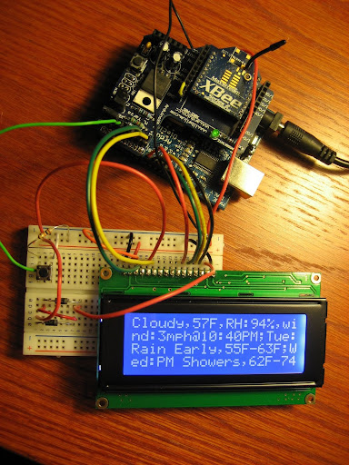
This is an Arduino based wireless device that can display arbitrary content (weather, news etc) at the touch of a button, via an XBee radio. Currently it supports weather by zip code and displays on a 4x20 LCD, but it's designed to easily expand to additional services. Some ideas for other services include: calendar events, traffic, next bus/train, tweets, news, mail, adjust thermostat, next track (itunes), turn on/off/dim light etc. This is mostly useful for quick information when you are not close enough to a computer (nightstand, living room, kitchen etc.) I chose weather as the initial service since it's relatively useful and part laziness since my wife asks me for the forecast every morning so she can plan her outfit.

How it Works

The system consists of a Service Gateway and one or more remote Arduinos. The remote Arduino consists of an XBee radio, LCD, and one or more buttons that are hardwired to a particular service (e.g. weather, news). When the button is pressed, it uses the XBee-Arduino library to send an XBee packet to the Service Gateway and displays the subsequent response on the LCD.


The Service Gateway is an XBee-API application that connects to an XBee Coordinator. The Service Gateway receives the request from the remote XBee and sends back a packet containing character data for display on the LCD. The Service Gateway doesn't need to know anything about the remote Arduino; as long as they have the same Channel and PAN ID, they can communicate.


Parts List
* One thing to keep in mind about eBay orders from China is they can take 3 weeks or longer for delivery.
** You can substitute an Arduino for a lower cost variant such as Adafruit's Boardino and corresponding XBee Adapter Kit
*** It's possible to substitute with Series 1 (802.15.4) XBees but this will require some code modifications.

Installation and Setup

The first order of business is to configure the XBees. You should have two series 2 XBee radios, one configured with coordinator firmware and the other with end device firmware. I'm recommend using ZB Pro firmware. ZNet should also work but has a limit of 72 bytes per packet so you won't be able to use the entire 80 characters of the display.

Place your XBee coordinator in the USB Explorer and use X-CTU to apply the following configuration:

Click the "Restore" button to clear out any previous configurations

Set PAN ID to an arbitrary value. The end device must also use this exact value

ID=1AAA

Set the node identifier to an arbitrary string. This serves as a convenient way to identify your devices
NI=COORDINATOR

Set API mode to 2 (escape control bytes)
AP=2

Click the "Write" button to save the configuration

Be sure to take note of the Serial High (SH) and Serial Low (SL) values as you will need this later

Now place your XBee end device in the USB Explorer and configure. If you are using ZB Pro firmware, this firmware does not support a disabled sleep option, so you need to perform a trick to keep the end device awake. See this blog entry for details. The end device configuration is identical to the coordinator except for the node identifier:

Click the "Restore" button

Set PAN ID to the same value as the coordinator

ID=1AAA

Set the node identifier to an arbitrary string.
NI=ARDUINOXBEE

Set API mode to 2 (escape control bytes)
AP=2

Click the "Write" button to save the configuration

Wire It Up

Now we're going to wire up the Arduino. Attach your Arduino XBee Shield to your Arduino and place your end device XBee in the shield.

Connect your LCD to a breadboard and wire to Arduino. I wired it up as follows but you can use any digital pins (except 13). This only requires 6 Arduino pins in 4-bit mode, woot! Here's the Winstar WH2004 LCD schematic for reference:

Pin 1 (VSS) - 5V
Pin 2 (Vdd) - GND
Pin 3 (Contrast) - GND
Pin 4 (RS) - Arduino Digital 6
Pin 5 (Read/Write) - GND
Pin 6 (Enable) - Arduino Digital 7
Pin 7 (Data Bus 0) - Arduino Digital 8
Pin 8 (Data Bus 1) - Arduino Digital 9
Pin 9 (Data Bus 2) - Arduino Digital 10
Pin 10 (Data Bus 3) - Arduino Digital 11
Pin 15 (Backlight Power)- 4.2V*
Pin 16 (Backlight Ground) - GND

All pins not listed should be left unconnected

* Now you might be wondering what to do about 4.2V when Arduino is 5V, I was. I found a nifty solution on the Arduino forum that involves a couple 1N4004 diodes to drop voltage close to 4.2. Each 1N4004 has a drop of around 0.7V. I probably could have used one but I ended up using two so I wouldn't go over the 4.2V. With two diodes I'm measuring 3.5V but this seems to work just fine. An LED should also work in place of a 1N4004.

Now connect a pushbutton input so that it provides 0V when depressed and of course 5V when open. Here's a great tutorial on Arduino and buttons.

Ok, so now we have everything wired up and it's time to load the software.

Software

We are using two Arduino libraries: XBee-Arduino and LCD4x20. The XBee-Arduino library provides XBee packet communication, allowing us to send requests for data and display responses on the LCD. The LCD4x20 Arduino Library is based on LCD4Bit but contains modifications to work specifically for a 4x20 HD44780 LCD. The problem with this particular LCD is that line 1 wraps to line 3, line 3 to line 2 and line 2 to line 4; this library corrects this problem and adds some additional features. Because this LCD doesn't shift character data properly, the library maintains a 80 byte buffer in order to perform shifts (e.g. line feed) by rewriting the character data to the display.

Download XBee-Arduino xbee-arduino-0.1.2.zip

Unzip and install in
ARDUINO_HOME/hardware/libraries

Download the LCD4x20 library and similarly install in

ARDUINO_HOME/hardware/libraries

Download the Service Gateway and Arduino Sketch for this project and unzip.

We're going to need to make a few changes to the Arduino Sketch. Open the Arduino sketch (in XBeeArduinoService/Arduino/XBeeArduinoLcd) and find the lines, starting with "rsPin" and specify the Arduino digital pin for each corresponding LCD pin. You don't need to change anything if you wired it according to my suggestions.
Now replace the 64-bit address on the following line with the (SH + SL) of your XBee coordinator. You copied it down, right?
XBeeAddress64 addr64 = XBeeAddress64(0x0013a200, 0x403e0f30);

Save the Sketch.

Upload the Sketch

While the Arduino is unpowered, set the USB/XBee jumpers on the Arduino XBee Shield to the USB position (this directs the Arduino's serial port to USB so we can upload). Connect the Arduino to your computer and upload the Sketch. Note: you may see a few warnings in red font -- this is ok. If successful, your LCD will be displaying a message: "XBeeArduinoLcd v1.0...".

Unplug the Arduino and return jumpers in the XBee position. Now you can power your Arduino externally and place anywhere within XBee range of your computer!

Now for the Service Gateway setup

Service Gateway

Download "Eclipse IDE for Java" for your platform from Eclipse and install (this usually involves only unzipping it).

Start Eclipse and select Import from the File menu. Expand the General folder and select "Existing Projects into Workspace".
Select File->New->Java Project
Give the project a name, maybe "XBeeArduinoService"
Check the "create project from existing source" radio button
Browse to the location where you unzipped the project and select the "XBeeArduinoService" folder
Hit "Finish"

It should automatically find the libraries and be ready to go.

In the left window, expand the project, the "src" folder and the "com.rapplogic.xbeearduinoservice" package. Now open XBeeArduinoWeatherService.java. We will need to update a few variables. At the top of the file, find the comPort variable and replace with the COM port of the USB Explorer. For Windows users, you can find the COM port by going to Start->(right-click)My Computer->Manage, then Select Device Manager and Ports. It should appear as USB Serial Port. For Mac users it will appear under /dev/tty.usbserial*, so an ls -l dev/tty.usbserial (tab tab) before and after the device is plugged in should tell you the com port.

The last change is to enter the zip code for your local weather:
Weather weather = getWeather("97007", true);
Save it. (Eclipse compiles it automatically)

Place your XBee coordinator in the USB Explorer and connect to your computer.

Now we need to create a Run Configuration:

Select "Run Configurations..." from the "Run" menu

Select "Java Application"

Press the "new" button icon

It should automatically find "com.rapplogic.xbeearduinoservice.XBeeArduinoWeatherService"

Click Run. Now that the service is running, press the Arduino button and get your weather!

Top stop the service, press the red square button. Now to start it again you only need to select "Run" from the "Run" menu.

Creating your own Services

To add another service you will need to wire a second push button to an available digital input on the Arduino. Then define the service with a unique number at the top of the Sketch, for example:

define ITUNES_NEXT_TRACK 2

Create a variable that holds the button's digital input:

int itunesButton = 3;

At the bottom of the file add a if statement to detect if the button was pressed:

if (digitalRead(itunesButton) == LOW) {
requestService(ITUNES_NEXT_TRACK);
}

For the Service Gateway, you'll need to write the code that implements the service and returns a String to be displayed on the LCD. Open the XBeeArduinoWeatherService.java (or create your own class) and add a call to your service method in processRequest method, like so:
protected String processRequest(int requestType) throws Exception {
switch (requestType) {
case 1:
// weather
Weather weather = getWeather("97007", true);
return weather.toString();
case 2: // matches the service id (ITUNES_NEXT_TRACK) in the Sketch
// itunes next track
return this.changeItunesTrackAndReturnSongInfo();
}
}
where you have defined a method
String changeItunesTrackAndReturnSongInfo() {
// changes the itunes track and returns the current song for display
...
}

The service will truncate the response to 80 characters since that is the size of the display.

The processRequest method must respond within getServiceTimeoutMillis() milliseconds (defaults to 6000 or 6 seconds) or it will timeout and send the "Application Timeout" message to LCD. You can change this timeout by calling setServiceTimeoutMillis method. However, if you change this timeout, you should also change the Arduino timeout (APPLICATION_TIMEOUT) to the same value, plus a buffer of 1 or 2 seconds. The buffer is necessary to account for the round trip packet transmission time. Packets are usually delivered in under 100ms but packet size, distance, interference, and all sorts of factors can result in delays.

Adding another remote Arduino is easy and requires no modifications to the Service Gateway. Just configure the remote Arduino with the same PAN ID (ID) and it will automatically join the network. You can add up to eight with a single coordinator and to scale beyond that you would just need to introduce a router.

What's Next?

Here are some ideas for phase 2:

- "Continue" feature to handle messages larger than 80 characters (LCD screen size)
- LCD menu system for accessing more services than we have available digital inputs
- Low power remote. Without the LCD backlight, and by putting the XBee in sleep mode, the remote Arduno could be powered by batteries, making it much more mobile
- Alert framework. Alerts are initiated by the Java service and displayed on the LCD. An example might be a twitter tweet or meeting reminder. Alerts would initiate a LED blinking routine to capture ones attention.
- Low power device such as the BeagleBoard to replace a PC as the service gateway. I don't like the idea of leaving a computer on all the time as it wastes electricity. Right now I'm using an old notebook that doesn't use much power.
- A nice looking enclosure

Sunday, February 22, 2009

XBee ZB Pro Upgrade Pin Sleep Trick

While developing the XBee-API 0.5 release, I upgraded my series 2 (ZNet 2.5) radios to ZB (ZigBee PRO) firmware by following the Digi conversion instructions

I was able to perform the firmware flash for both radios: "API coordinator (1941)" and "API End Device (2941)", but when I attempted to read the End Device using X-CTU, I got the following error:

"Failed to enter command mode
Unable to read Version (ATVR)
Read parameters.. Failed."

After a few more attempts, the read succeeded but when I clicked "write" to save my configuration I got a similar error:

"Getting modem type....OK
Programming modem...Lost communication with modem
Write Parameters...Failed"

Woe ensues. As it turns out, the default sleep option for "API End Device (2941)" firmware is SM=4 (Cyclic Sleep); the errors occur because the radio is periodically going to sleep and waking up. Unfortunately SM=0 (No Sleep) isn't even supported in this firmware, but there is a solution. To simulate No Sleep, configure the radio to SM=1 (Pin Hibernate), and then connect Pin Sleep (pin 9) to Ground (pin 10). Credit goes to Hans (XBee-API user) for this idea.

Now to program the radio we still have to fix the sleep issue. To do this we can use the Reset pin (pin 5). The Reset is activated by connecting the Reset pin to Ground (pin 10), and then disconnecting. If you have a toggle switch handy you'll want to wire this to pin 5 and pin 10. (Remember if you are using, XBee Explorer USB, there are two extra pins (GND and 5V), as shown in the diagram)


Now toggle the switch on/off just before performing the X-CTU action (e.g. read/write). Once you have configured the radio to Pin Hibernate mode and grounded pin 9, the radio won't go to sleep and you won't need to use the Reset pin anymore.

Saturday, February 21, 2009

XBee Communication over Google Talk

I had been kicking this idea around since early last year but progress was slow until recently. So what happens when we have stretches of frigid, bleak weather? I end up coding, a lot. The end result is XBee-XMPP, which I released a few weeks ago on Google Code.


This project builds on XBee-API and provides a solution to talk to your XBee network from anywhere on the internet, using XMPP.

Now you can sit back in your favorite chair or couch and write code to communicate with your XBee radios, without cables, and/or breadboards dangling off your notebook. You can even share your XBee network with your friends. It doesn't even matter if your application is behind a firewall (e.g school/work/home), because as long as you can reach the XMPP server (Google Talk or Openfire), you can talk to the XBee network. With this solution, your XBee applications run in separate processes, so they can stopped, started, upgraded etc, all without affecting your other applications.

This project uses Smack for XMMP communication. Initially I'm supporting Openfire and Google Talk, but any XMPP service should be possible. Google Talk is recommended for getting up and running quickly because you don't need to setup a server; you just need two Google Talk accounts.

Sunday, January 18, 2009

Arduino LED Color Picker


After experimenting with an RGB LED for a while, I became interested in the idea of using a color gradient to control the LED. I search around a bit for a color gradiant library and finally settled on colorpicker, a subproject of colorchooser (scroll down the page for colorpicker). This library is surprisingly easy to integrate with and allows you to receive color events in real-time, as you drag the mouse around the gradient.

Since this solution is written in Java and uses the same serial library (RXTX) as Arduino, it will run on any platform that Arduino supports (Windows/Mac/Linux etc.). I have included RXTX libraries in the download so it will run on any of these platforms, out-of-the-box (box not included).

Here's a quick video of the application in action:


The application consists of Java application that serves as the colorpicker interface and an Arduino Sketch that receives RGB colors and applies them to the PWM pins

The basic process flow of the Java application is as follows:

- Open serial port to Arduino
- Initialize colorpicker component and register an event handler
- (In forever loop)
- Wait for colorpicker event.
- Send color to Arduino
- Wait for reply from Arduino (ACK)

The colorpicker runs in a separate thread and sends color events to the main thread.

The Java application sends the RGB colors in a sequence of four bytes: red, green, blue and a EOT byte. The EOT byte signals the end of a color sequence and instructs the Arduino to process the color. Since a byte has 256 values and we need all of them for the color values, I created a escape byte (0x2) to distinguish the EOT byte (0x1) from the color value (0x1). Any time a color value of 0x1 or 0x2 is sent, it is preceded by a escape byte and XOR'd with 0x20. When the Arduino receives the data via Serial.read(), it performs a corresponding XOR operation to un-escape the bytes.

Once the Arduino processes the color, it sends an ACK byte back to the Java application, so that it can send the next color. Without the ACK byte, we run the chance of overflowing the buffer by sending color events faster than the Arduino can process them.

Here's the Arduino sketch:


// Adjust as necessary to match your RGB LED. Remember to only use the PWM pins
int redPin = 11;
int greenPin = 10;
int bluePin = 9;

// Indicates what color we are reading next; 0 = red, 1 = green, 2 = blue
int pos = 0;

// red PWM value
int red = 0;
// green PWM value
int green = 0;
// blue PWM value
int blue = 0;

// indicates if next byte should be unescaped
boolean escape = false;

void setup() {
pinMode(redPin, OUTPUT);
pinMode(greenPin, OUTPUT);
pinMode(bluePin, OUTPUT);

Serial.begin(9600);

// turn on LED on low brightness
analogWrite(redPin, 16);
analogWrite(greenPin, 16);
analogWrite(bluePin, 16);
}

void loop () {

while (Serial.available()) {
int rgb = Serial.read();

if (rgb == 1) {
// end of RGB sequence byte
// reset pos
pos = 0;

// process this color
analogWrite(redPin, red);
analogWrite(greenPin, green);
analogWrite(bluePin, blue);

// Send ACK byte so Java app can send the next color
Serial.print("k");
Serial.flush();

// get next byte
continue;
} else if (rgb == 2) {
// escape byte
escape = true;
// discard byte and read next byte
continue;
}

if (escape) {
// unescape byte
rgb = 0x20 ^ rgb;
// reset escape
escape = false;
}

switch (pos++) {
case 0:
red = rgb;
break;
case 1:
green = rgb;
break;
case 2:
blue = rgb;
break;
}
}
}

To run the app, first download the project from my Google Code project. I've included the full Java source code and everything necessary to run the app, sans Java.

Next, connect your RGB LED to the Arduino PWM pins, as specified in the Arduino sketch. Be sure to use appropriate resistors so that you do not draw more current than the Arduino can supply. If you need a RGB LED, here's a basic one offered by SparkFun . You could also use separate Red, Green and Blue LEDs and diffuse the colors with something like a paper box.

Now upload the sketch to your Arduino.

If you don't have Java 1.5 or later, now would be a good time to get it. You can find out by opening a command prompt/shell and typing "java -version" If you see something like this then you are all set:

java version "1.5.0_16"
Java(TM) 2 Runtime Environment, Standard Edition (build 1.5.0_16-b06-284)
Java HotSpot(TM) Client VM (build 1.5.0_16-133, mixed mode, sharing)


Before running the Java application you need to open the run script for your platform and specify the COM port of your Arduino:

Windows: ledcolorpicker.cmd
Mac/Linux: ledcolorpicker.sh

The COM port should be the last argument on the line that starts with "java"

Now run the script for your platform:

Windows: double-click on ledcolorpicker.cmd (note: if the window closes immediately, open a command prompt and run the script again to get the error)

Mac/Linux: First you probably need to make it executable: "chmod u+x ledcolorpicker.sh". Now run the script "./ledcolorpicker.sh"

The LedColorPicker application should now start up and be ready to go.

Based on my results, the Arduino processes colors in about 16ms -- that is time it takes to send a color to the Arduino and receive an ACK @ 9600 baud. I've found that the Arduino can process color events almost as fast as the colorpicker can generate events. In my limited testing, only less than 2% of color events were discarded because the Arduino was busy processing a previous color. You could use a higher baud rate but with this level of performance it's not necessary. This translates to the Arduino processing about 30 colors changes per second -- not bad.

You may have noticed that we are tethered to our computer in this configuration. The good news is it's possible to make this solution wireless with minimal effort, using with XBee radios. Using the Arduino XBee Shield configured in transparent mode, you could put your LED across the room or anywhere within range and control it from your PC. In this configuration you would need two XBee radios, 1 Arduino XBee Shield and 1 USB-Serial device with XBee socket, such as the SparkFun's XBee Explorer.